background image

22 – 

English

STARTING AND STOPPING

Warm engine

Ignition:

 Set the stop switch to the start position.

Choke:

 Put the choke in working position.

Primer bulb:

 Press the primer bulb repeatedly until fuel 

begins to fill the bulb. The bulb need not be completely filled.

For throttle handles with a start throttle 
lock:

Set the throttle to the start position by first pressing the throttle 
lock and the throttle trigger, then pressing the start throttle 
button (A). Then release the throttle lock and the throttle 
trigger, followed by the start throttle button. The throttle 
function is now activated. To return the engine to idle, press 
the throttle lock and throttle trigger again.

PART THROTTLE  FUNCTION

It is possible to set the engine for part throttle operation using 
the dial on the side of the throttle handle. Turn the dial up to 
decrease the part throttle rpm. Turn the dial down to increase 
the part throttle rpm. When you have set the part throttle rpm 
you will feel increased resistance when you press the throttle 
trigger. This increased resistance makes it easier to maintain 
a constant part throttle setting. To obtain full throttle, press the 
throttle trigger a little harder so that it goes past the part 
throttle setting. As soon as you release the throttle trigger the 
engine will return to idle. The part throttle function does not 
lock the engine at a given rpm, it is simply a brake that makes 
it easier to maintain the engine at a given rpm.

Starting

Hold the body of the machine on the ground using your left 
hand (CAUTION! Not with your foot!). Grip the starter handle, 
slowly pull out the cord with your right hand until you feel 
some resistance (the starter pawls grip), now quickly and 
powerfully pull the cord. 

Never twist the starter cord around 

your hand.

Repeat pulling the cord until the engine starts. When the 
engine starts. return choke control to run position and apply 
full throttle; the throttle will automatically disengage from the 
start setting.

CAUTION! Do not pull the starter cord all the way out and do 
not let go of the starter handle when the cord is fully extended. 
This can damage the machine.

Stopping

Stop the engine by switching off the ignition.

O

I

L

!

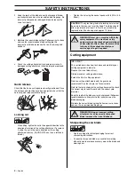
WARNING! When the engine is started with 
the choke in either the choke or start throttle 
positions the cutting attachment will start to 
rotate immediately.

Summary of Contents for 324R X-Series

Page 1: ...E E E En n n ng g g gl l l li i i is s s sh h h h 324RX SERIES Operator s manual Please read the operator s manual carefully and make sure you understand the instructions before using the machine ...

Page 2: ... when the blade comes into contact with a fixed object The blade is capable of amputating an arm or leg Always keep people and animals at least 15 metres from the machine Arrows which show limits for handle positioning Always wear approved protective gloves Wear sturdy non slip boots Only use non metallic flexible cutting attachments i e trimmer heads with trimmer cord Noise emission to the enviro...

Page 3: ... cutting attachments 18 Adjusting the harness and clearing saw 19 Standard harness 19 FUEL HANDLING Fuel 20 STARTING AND STOPPING Check before starting 21 Starting and stopping 21 MAINTENANCE Carburettor 23 Muffler 23 Cooling system 23 Spark plug 23 Air filter 24 Sharpening grass cutters and grass blades 24 Sharpening the saw blade 25 Maintenance schedule 26 TECHNICAL DATA Technical data 27 EC dec...

Page 4: ...an of the machine can be reduced and the risk of accidents can increase if machine maintenance is not carried out correctly and if service and or repairs are not carried out professionally If you need further information please contact your nearest service workshop Throttle lock The throttle lock is designed to prevent accidental operation of the throttle control When you press the lock A i e when...

Page 5: ...ust gases In countries that have a warm and dry climate there is a significant risk of fire We therefore fit certain mufflers with a spark arrestor mesh Check whether the muffler on your machine is fitted with this kind of mesh For mufflers it is very important that you follow the instructions on checking maintaining and servicing your machine See instructions under the heading Checking maintainin...

Page 6: ...the handle the throttle control and the throttle lock both move back to their original positions This movement is controlled by two independent return springs This arrangement means that the throttle control is automatically locked at the idle setting WARNING Bear in mind that Engine exhaust fumes contain carbon monoxide which can cause carbon monoxide poisoning For this reason you should not star...

Page 7: ...you are using See chapter on Technical data Vibration damping system Regularly check the vibration damping units for cracks or deformation Check that the vibration damping element is undamaged and securely attached Muffler Never use a machine that has a faulty muffler Regularly check that the muffler is securely attached to the machine If the muffler on your machine is fitted with a spark arrestor...

Page 8: ...ade is essential for working efficiently and to avoid unnecessary wear to the blade and clearing saw CAUTION The nylon lining inside the locking nut must not be so worn that you can turn it by hand The lining should offer a resistance of at least 1 5 Nm The nut should be replaced after it has been put on approx 10 times WARNING Never use a machine with faulty safety equipment The machine s safety ...

Page 9: ... when a fully automatic trimmer head is used Only use the recommended cutting attachment See the chapter on Technical data Smaller machines generally require small trimmer heads and vice versa This is because when clearing using a cord the engine must throw out the cord radially from the trimmer head and overcome the resistance of the grass being cleared The length of the cord is also important A ...

Page 10: ...rical relays switches or boilers When storing and transporting fuel always use approved containers intended for this purpose When storing the machine for long periods the fuel tank must be emptied Contact your local petrol station to find out where to dispose of excess fuel IMPORTANT The machine is only designed for trimming grass grass clearing and or forestry clearing The only accessories you ca...

Page 11: ...e running unless you have it in clear sight Adjusting the harness and clearing saw Safety release At the front is an easily accessible quick release Use this if the engine catches fire or in any other emergency situation that requires you to free yourself from the machine and harness Spreading the load on your shoulders A well adjusted harness and machine makes work much easier Adjust the harness ...

Page 12: ...d stones Working methods Before you start clearing check the clearing area the type of terrain the slope of the ground whether there are stones hollows etc On sloping ground you should work along the slope It is much easier to work along a slope than it is to work up and down it The strip should be planned so that you avoid going over ditches or other obstacles on the ground Brush cutting with a s...

Page 13: ...ive bark on trees and bushes and damage fence posts Reduce the risk of damaging plants by shortening the cord to 10 12 cm and reducing the engine speed Clearing The clearing technique removes all unwanted vegetation Keep the trimmer head just above the ground and tilt it Let the end of the cord strike the ground around trees posts statues and the like CAUTION This technique increases the wear on t...

Page 14: ...u should use full throttle to obtain the best results WARNING Neither the operator of the machine nor anyone else may attempt to remove the cut material while the engine is running or the blade is rotating as this can result in serious injury Stop the engine and blade before you remove material that has wound around the blade shaft as otherwise there is a risk of injury The bevel gear can get hot ...

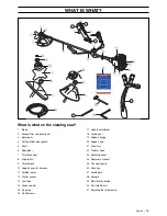
Page 15: ...ck 10 Support eyes for harness 11 Cylinder cover 12 Starter handle 13 Fuel tank 14 Choke control 15 Air purge 16 Air filter cover 17 Handle adjustment 18 Locking nut 19 Support flange 20 Support cup 21 Drive disc 22 Trimmer head 23 Socket spanner 24 Operator s manual 25 Transport guard 26 Allen key 27 Locking pin 28 Harness 29 Start throttle button 30 Part throttle dial 31 Adjusting the throttle w...

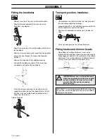
Page 16: ... handlebar can easily be turned to fit along the shaft for easier transportation and storage Loosen the knob Turn the handlebar clockwise so that the throttle handle rests against the engine Now twist the handlebar around the shaft Tighten the knob Fit the transport guard to the cutting attachment Fitting blades and trimmer heads When fitting the cutting attachment it is extremely important that t...

Page 17: ... Fit the adapter I and bracket J with the two screws K as shown Fit the blade guard A to the adapter using the 4 screws L as shown CAUTION Use the recommended blade guard See the Technical data section Fit the drive disc B on the output shaft Turn the blade shaft until one of the holes in the drive disc aligns with the corresponding hole in the gear housing Insert the locking pin C in the hole to ...

Page 18: ...he support flange F on the output shaft Fit the nut G Tighten the nut to a torque of 35 50 Nm 3 5 5 kpm Use the socket spanner in the tool kit Grasp the handle of the spanner as close to the trimmer guard as possible To tighten the nut turn the spanner in the opposite direction to the direction of rotation Caution left hand thread Fit the bottom half of the trimmer head K to the cover I by pressin...

Page 19: ...weight is evenly distributed across both shoulders Correct height Adjust the shoulder strap so that the cutting attachment is parallel to the ground Correct balance Let the cutting attachment rest lightly on the ground If you use a saw blade it should balance about 10 cm above the ground to prevent contact with stones and the like Adjust the position of the support hook to balance the clearing saw...

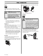
Page 20: ...rew the oil cap clean the dipstick located on the cap and insert the cap again without screwing it down Check the oil level on the dipstick When the oil level is low top up using engine oil to the edge of the oil refill hole Only use recommended engine oil Fuelling Clean around the fuel cap Clean the fuel and oil tank regularly The fuel filter should be changed at least once a year Contamination i...

Page 21: ...er head and trimmer guard are not damaged or cracked Replace the trimmer head or trimmer guard if they have been exposed to impact or are cracked Never use the machine without a guard nor with a defective guard All covers must be correctly fitted and undamaged before you start the machine Starting and stopping Cold engine Ignition Set the stop switch to the start position Choke Set the choke contr...

Page 22: ...maintain a constant part throttle setting To obtain full throttle press the throttle trigger a little harder so that it goes past the part throttle setting As soon as you release the throttle trigger the engine will return to idle The part throttle function does not lock the engine at a given rpm it is simply a brake that makes it easier to maintain the engine at a given rpm Starting Hold the body...

Page 23: ...uld be cleaned regularly A blocked mesh will cause the engine to overheat and may lead to serious damage CAUTION Never use a machine with a defective muffler Cooling system To keep the working temperature as low as possible the machine is equipped with a cooling system The cooling system consists of 1 Air intake on the starter 2 Fins on the flywheel 3 Cooling fins on the cylinder 4 Cylinder cover ...

Page 24: ...ions the air filter should be soaked in oil See instructions under the heading Oiling the air filter Oiling the air filter Always use HUSQVARNA filter oil art no 531 00 92 48 The filter oil contains a solvent to make it spread evenly through the filter You should therefore avoid skin contact Put the filter in a plastic bag and pour the filter oil over it Knead the plastic bag to distribute the oil...

Page 25: ... and those in between to the left If the blade has been heavily pitted by stones it may be necessary to dress the top edges of the teeth with a flat file in exceptional cases If so this should be done before filing with a round file The top edges must be filed down by the same amount for all the teeth Adjust the blade setting This should be 1 mm WARNING Always discard a blade that is bent twisted ...

Page 26: ...for the blade is intact and that it can be secured correctly 14 Check that nuts and screws are tight 15 Check that there are no fuel leaks from the engine tank or fuel lines 16 Check that the screws that hold the bevel gear are tight Weekly maintenance 1 Check the starter and starter cord 2 Check that the vibration damping elements are not damaged 3 Clean the outside of the spark plug Remove it an...

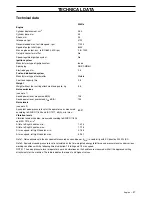
Page 27: ... output shaft rpm 8300 Max engine output acc to ISO 8893 kW rpm 0 8 7000 Catalytic converter muffler No Speed regulated ignition system No Ignition system Manufacturer type of ignition system Ikeda Spark plug NGK CMR5H Electrode gap mm 0 6 Fuel and lubrication system Manufacturer type of carburettor Walbro Fuel tank capacity litre 0 5 Weight Weight without fuel cutting attachment and guard kg 5 5 ...

Page 28: ...teeth 503 93 42 02 Saw blade Maxi X 200 26 1 Ø 200 26 teeth 537 21 71 01 Scarlet 200 22 1 Ø 200 22 teeth 537 21 71 01 Plastic blades Tricut Ø 255 mm 503 93 42 02 503 97 71 01 Tricut Ø 300 mm 503 93 42 02 Trimmer head Trimmy Fix 503 93 42 02 503 97 71 01 Superauto II 1 503 93 42 02 503 97 71 01 S35 503 93 42 02 503 97 71 01 T25 503 93 42 02 503 97 71 01 T35 503 93 42 02 503 97 71 01 Support cup Fix...

Page 29: ...ry 98 37 EC annex IIA of May 3 1989 relating to electromagnetic compatibility 89 336 EEC and applicable supplements of May 8 2000 relating to the noise emissions in the environment 2000 14 EC For information relating to noise emissions see the chapter Technical data The following standards have been applied EN292 2 CISPR 12 1997 EN ISO 11806 SMP Svensk Maskinprovning AB Fyrisborgsgatan 3 SE 754 50...

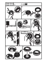
Page 30: ...1 Super Auto II Super Auto II 1 2 3 4 5 6 7 8 9 10 4 0 m 13 2 4 mm 095 2 0 m 6 5 6 6 15 cm 15 cm ...

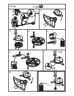
Page 31: ......

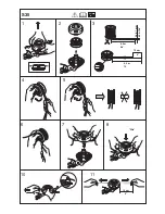
Page 32: ... Clic 1 2 3 5 6 7 10 11 8 5 m 28 4 8 4 2 m 14 2 4 2 7 mm 095 106 10 cm 4 6 15 cm S35 ...

Page 33: ...1 2 4 3 2 4 2 7 mm 095 106 4 25 m 14 4 25 m 14 B 6 15 cm A 6 15 cm S35 5 ...

Page 34: ... z H9r 6 z H9r 6 T35 Clic 1 2 3 5 6 7 9 8 5 m 28 4 8 4 3 m 14 2 4 2 7 mm 095 106 10 cm 4 6 15 cm ...

Page 35: ......

Page 36: ... z H9r 6 2004 04 08 z H9r 6 1140258 26 ...

Reviews: