background image

22 

– English

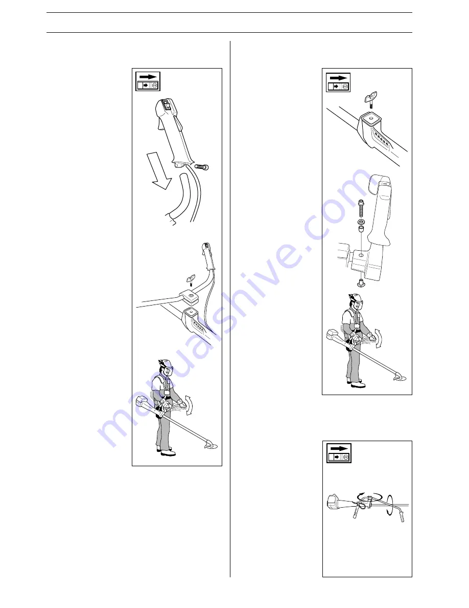
Assembling the handlebars (240R,
245R, 250R)

ASSEMBLY

• The handlebars can easily

be turned to fit along the
shaft for easy
transportation and storage.

• Loosen the knob. Turn the

handles clockwise so that
the throttle comes against
the engine.

• Thereafter fold the

handlebars around the
shaft. Tighten the handle.

• Attach the transport guard.

• Unscrew the handle from

the handlebar bracket.

• Position the handlebars as

shown. Fit the bracket
components and tighten
the handle lightly.

• Fit the right hand grip to

the handlebar using the
bolt, washer, sleeve and
nut as shown. Tighten the
bolt.

• Put on the harness and

hang the machine in the
suspension hook. Now
finely adjust so that the
machine gives a
comfortable working
position when it‘s attached
to the harness. Tighten the
handle.

• Remove the screw at the

rear of the throttle handle.

• Slide on the throttle

handle on the right-hand
side of the handlebars, (see
the diagram).

• Align the hole in the

throttle handle for the
fixing screw with the hole
on the handlebars.

• Refit the screw in the rear

of the throttle handle.

• Fit the screw through the

throttle handle and the
handlebars and tighten.

• Unscrew the handle from

the handlebar bracket.

• Position the handlebars as

shown. Fit the bracket
components and tighten
the handle lightly.

• Put on the harness and

hang the machine in the
suspension hook. Now
finely adjust so that the
machine gives a
comfortable working
position when it‘s attached
to the harness. Tighten the
handle.

Assembling the handlebars (245RX,
252RX)

Transport position, handlebars
(240R, 245R/RX, 250R, 252RX)

Summary of Contents for 240R

Page 1: ...Operator s manual EPA 240R 245R RX 250R 252RX 265RX Please read these instructions carefully and make sure you understand them before using the machine English ...

Page 2: ...able CE directives Beware of thrown objects and ricochets 50FT 15 m 50FT 15 m The operator of the machine shall ensure while working that no persons or animals come closer than 15 metres Machines fitted with clearing or grass blades can be thrown violently to the side when the blade comes into contact with a fixed object The blade can cause the amputation of arms and legs Always keep people and an...

Page 3: ...rt and stop 27 MAINTENANCE Carburetor 29 Muffler 31 Cooling system 31 Air filter 32 Angle gear 33 Spark plug 33 Sharpening the grass blade 33 Sharpening the clearing blade 34 Maintenance schedule 34 TECHNICAL DATA 240R 245R 245RX 35 250R 252RX 265RX 36 FEDERAL AND CALIFORNIA EMISSION CONTROL WARRANTY STATEMENT Your warranty rights and obligations 38 Husqvarna AB has a policy of continuous product ...

Page 4: ...en fatal injury to the operator or others It is extremely important that you read and understand the content of this manual When using a clearing saw brushcutter or trimmer protective equipment approved by the appropriate authorities must be used Personal protective equipment does not eliminate the risk of accidents however it can reduce the effects of an injury in the event of an accident Ask you...

Page 5: ... the proper parts can cause the blade to fly off and seriously injure the operator and or bystanders Under no circumstances may the cutting equipment be used without an approved guard fitted See the chapter Technical data If the wrong guard or a defective guard is fitted this can cause serious personal injury WARNING Over exposure to vibrations can result in blood vessel or nerve injury to persons...

Page 6: ...maintenance and service of the machine s safety equipment 7 Cutting equipment 1 Clearing blades are intended for cutting wood 2 Grass blades are intended for brush cutting 3 The trimmer head is intended for trimming grass 2 1 3 8 Locking nut A locking nut is used to secure some types of cutting equipment on the output shaft WARNING Mufflers fitted with catalytic converters become extremely hot dur...

Page 7: ...y locked in its idling position Control maintenance and service of the machine s safety equipment IMPORTANT INFORMATION All service and repairs to the machine require special training This applies especially to the machine s safety equipment If the machine does not meet any of the controls listed below you should contact your service workshop The purchase of one of our products guarantees that pro...

Page 8: ...that has a defective muffler 2 Check regularly that the muffler is secure 3 If your muffler is fitted with a spark arrest screen then it should be cleaned regularly A blocked screen leads to the engine overheating with serious damage as a result Never use a muffler with a defective spark arrest screen 4 Vibration damping system Check the vibration damping element regularly for material cracks and ...

Page 9: ...our instructions and use the recommended setting tool An incorrectly set blade increases the risk of jamming and kickback 4 Check the cutting equipment with regard to damage and crack formation Damaged cutting equipment should always be replaced WARNING Never use a machine with defective safety equipment The safety equipment should be maintained as described in this section If your machine does no...

Page 10: ...of the cord it can be soaked in water for a few days This will make the line tougher and it will keep longer Sharpening the clearing blade See the cutting equipment s packaging for correct filing instructions A correctly sharpened blade is a prerequisite for working efficiently and to avoid unnecessary wear to the blade and clearing saw Make sure that the blade is well supported when you use the f...

Page 11: ...is started otherwise the clutch can become loose and cause personal injury Never start the machine indoors Bear in mind the dangers of inhaling the engine s exhaust fumes Observe your surroundings and make sure that there is no risk of people or animals coming into contact with the cutting equipment Place the machine on the ground ensure the cutting equipment runs free of twigs and stones Push the...

Page 12: ...h the cutting equipment or objects that can be thrown by the cutting equipment NOTE Never use a machine without the possibility of calling for help in the event of an accident 2 Avoid usage in unfavourable weather conditions For example thick fog heavy rain strong winds or extreme cold etc To work in bad weather conditions is tiring and can create dangerous circumstances e g slippery surfaces affe...

Page 13: ...y other emergency situation when you quickly need to take off the harness and machine Even load on the shoulders A well adjusted harness and clearing saw significantly facilitates working Adjust the harness for the best working position Tension the side straps so that the weight is evenly distributed across the shoulders Correct height 1 Forestry clearing Adjust the carrier strap so that the suspe...

Page 14: ...ground the pathway should run parallel to the slope It is far easier to work along a slope then up and down a slope The pathway should be planned so that you avoid going over ditches or other obstacles Also adapt the pathway to the wind conditions so that the cleared stems fall on the part of the stand that has been cleared Forestry clearing using a saw blade When applying the blade to heavier ste...

Page 15: ...gine and blade before you remove material that has wound around the blade as otherwise there is a risk of injury The bevel gear unit can get hot during use and may remain so for a while afterwards There is a risk of slight burns if you touch it WARNING Beware of thrown objects Always wear eye protection Never lean over the guard Stones rubbish etc can be thrown up into the eyes resulting in blindn...

Page 16: ...n trimming and clearing you should use less than full throttle so that the cord lasts longer and to reduce the wear on the trimmer head Trimming The trimmer is ideal to cut grass that is difficult to reach using a normal lawn mower Keep the cord parallel to the ground when cutting Avoid pressing the trimmer head against the ground as this can ruin the lawn and damage the tool Do not allow the trim...

Page 17: ...ard 5 Shaft 6 Handlebars 7 Throttle 8 Stop switch 9 Throttle trigger lock 10 Suspension for clearing saw 11 Cylinder cover 12 Starter handle 13 Fuel tank 14 Choke 17 Handlebar adjustment 18 Locking bolt 19 Support flange 20 Support cup 21 Drive disc 22 Trimmer head 25 Socket spanner 26 Operator s Manual 27 Transport guard 28 Allen key 29 Carburetor screwdriver 30 Locking pin 31 Harness 32 Spray gu...

Page 18: ...29 Carburetor screwdriver 30 Locking pin 31 Harness 245RX What is what on the trimmer brushcutter 245RX 1 Blade 2 Grease filler cap 3 Angle gear 4 Blade guard 5 Shaft 6 Handlebars 7 Throttle 8 Stop switch 9 Throttle trigger lock 10 Suspension for clearing saw 11 Cylinder cover 12 Starter handle 13 Fuel tank 14 Choke 6 18 19 1 4 21 26 27 29 30 25 28 31 3 2 5 13 10 9 8 7 17 11 12 14 ...

Page 19: ...ft 6 Handlebars 7 Throttle 8 Stop switch 9 Throttle trigger lock 10 Suspension for clearing saw 11 Cylinder cover 12 Starter handle 14 Choke 15 Air filter 16 Fuel tank 17 Handlebar adjustment 18 Locking bolt 19 Support flange 20 Support cup 21 Drive disc 25 Socket spanner 26 Operator s Manual 27 Transport guard 28 Allen key 29 Carburettor screwdriver 30 Locking pin 31 Harness 32 Gearbox grease 33 ...

Page 20: ...or screwdriver 30 Locking pin 31 Harness 32 Gearbox grease 1 3 2 4 8 9 7 27 4 1 19 18 21 29 30 28 25 31 5 6 17 10 11 12 16 15 14 26 32 What is what on the clearing saw 252RX 1 Blade 2 Grease filler cap 3 Angle gear 4 Blade guard 5 Shaft 6 Handlebars 7 Throttle 8 Stop switch 9 Throttle trigger lock 10 Suspension for clearing saw 11 Cylinder cover 12 Starter handle 14 Choke 15 Air filter 16 Fuel tan...

Page 21: ...tor screwdriver 30 Locking pin 31 Harness 32 Gearbox grease 18 19 1 4 21 31 12 13 11 15 14 10 9 8 7 5 3 1 2 29 30 28 26 27 6 17 32 25 265RX What is what on the clearing saw 265RX 1 Blade 2 Grease filler cap 3 Angle gear 4 Blade guard 5 Shaft 6 Handlebars 7 Throttle 8 Stop switch 9 Throttle trigger lock 10 Suspension for clearing saw 11 Cylinder cover 12 Starter handle 13 Fuel tank 14 Choke ...

Page 22: ...e machine gives a comfortable working position when it s attached to the harness Tighten the handle Remove the screw at the rear of the throttle handle Slide on the throttle handle on the right hand side of the handlebars see the diagram Align the hole in the throttle handle for the fixing screw with the hole on the handlebars Refit the screw in the rear of the throttle handle Fit the screw throug...

Page 23: ...htly Then make the final adjustment with the clearingsaw in the harness to obtain the most suitable working position Tighten the screws Make a final adjustment of the right handle and fix it in the most comfortable position Adjusting the throttle control Adjust the throttle control for the most suitable working position Use the socket head screws at the right handle ...

Page 24: ...ng equipment assembled incorrectly can result in serious and or fatal personal injury G F E D B C A L M spanner as close to the blade guard as possible The nut is tightened when the spanner is turned against the direction of rotation left hand thread The guard A is fitted using 4 screws L and the support plate M as set out in the diagram NOTE Use the recommended blade guard Fit the drive disc B on...

Page 25: ...oulders Correct height 1 Forestry clearing Adjust the carrier strap so that the suspension hook comes approximately 10 cm under the hip The blade should be angled forward a little 2 Grass clearing The suspension hook should hang approximately 20 cm under the hip so that the blade is parallel to the ground Correct balance 1 Forestry clearing Move the suspension eye forwards or backwards If the blad...

Page 26: ...er muffler gets very hot during and after use This also applies during idling Be aware of the fire hazard especially when handling the saw near flammable substances or vapours Min 3 m 10 ft NOTE The machine is fitted with a two stroke engine and must always be run on a mixture of gasoline and two stroke oil It is important to measure the quantity of oil accurately to ensure the correct mixture rat...

Page 27: ... much Discard the support flange if it is cracked Ensure the locking nut has not lost its captive force The nut lock should have a locking force of at least 1 5 Nm The tightening torque of the locking nut should be 35 50 Nm Check that the guard is not damaged or cracked Replace the guard if it is exposed to impact or is cracked Check that the trimmer head and spray guard are not damaged or cracked...

Page 28: ...er handle slowly pull out the cord with your right hand until you feel some resistance the starter pawls grip now quickly and powerfully pull the cord Reset the choke control as soon as the engine fires and repeat until the engine starts When the engine starts quickly apply full throttle and the start throttle will automatically disengage NOTE Do not pull the starter cord out completely and do not...

Page 29: ...e filter is finally cleaned This can give rise to serious engine damage Carefully turn the L and H needle to the mid point between fully turned in and fully turned out Do not attempt to adjust the needles beyond the stops as damage can occur Now start the machine according to the starting instructions and run it warm for 10 minutes NOTE If the cutting attachment rotates moves the T screw should be...

Page 30: ...le H gives lower power less capacity bad acceleration and or damage to the engine A too rich adjustment of the two speed needles L and H gives acceleration problems or too low working speed MAINTENANCE High speed needle H The high speed needle affects the machine s power speed temperature and fuel consumption A too lean adjustment on the high speed needle H the high speed needle H is screwed in to...

Page 31: ...d towards a dry and inflammable mate rial Some mufflers are equipped with a special spark arrest screen If your machine is fitted with this type of screen it should be cleaned regularly This is done using a wire brush On mufflers without a catalytic converter the screen should be cleaned weekly or replaced if necessary On mufflers fitted with a catalytic converter the screen should be checked and ...

Page 32: ... Filter A must then be soaked in oil see the section on Oiling the air filter 265RX Remove the air filter cover and take out the air filter Wash it clean in warm soapy water Ensure that the filter is dry before refitting Oiling the air filter Always use HUSQVARNA filter oil order no 503 47 73 01 The filter oil contains a solvent to make it spread evenly through the filter You should therefore avoi...

Page 33: ...nd at the same time check that the electrode gap is 0 5 mm The spark plug should be changed after about one month of operation or earlier if necessary NOTE Always use the recommended type of spark plug An incorrect spark plug can damage the cylinder piston WARNING Always stop the engine before starting work on any part of the cutting equipment This continues to rotate even after the throttle has b...

Page 34: ... harness is undamaged Check the blade guard for damage or cracks Change the guard in case of impacts or cracks Check that the blade is properly centred sharp and without cracks Check the trimmer head for cracks and chips or damage Replace if necessary A non balanced blade trimmer head induces heavy vibrations that may damage the machine Check that the blade nut is sufficiently tightened Make sure ...

Page 35: ...ISO 10884 dB A min max Vibration levels Vibration levels on the handles measured according to prEN 31806 and ISO 7916 m s2 When idling left right handles min When idling left right handles max At max speed left right handles min At max speed left right handles max NOTE The noise and vibration measurments are made with all for the machine approved cutting equipment The maximum and minimum values ar...

Page 36: ...max Vibration levels Vibration levels on the handles measured according to prEN 31806 and ISO 7916 m s When idling left right handles min When idling left right handles max At max speed left right handles min At max speed left right handles max 265RX 65 1 48 36 2 250 11 500 9 120 3 0 kW 8 400 rpm No SEM GA 6CD Champion RCJ 7Y 0 5 Tillotson HS 1 0 10 8 98 100 112 113 4 5 4 0 5 1 4 6 3 0 3 9 3 9 5 1...

Page 37: ... 03 502 03 95 03 503 91 60 01 503 91 60 01 Cutting attachment guard Art No 502 12 26 01 502 26 34 01 502 26 34 01 502 27 22 01 502 03 94 03 503 91 60 01 502 26 34 01 503 91 60 01 503 91 60 01 Approved accessories 250R Centre hole in saw blades knives 20 mm Thread output axle M12 Grass blade grass knife Saw blade Plastic knives Trimmer head Support cup Type Multi 255 3 255 3 teeth Multi 275 4 275 4...

Page 38: ...equent purchaser that the engine is free from defects in materials and workmanship which cause the failure of a warranted part for a period of two years WHAT IS COVERED REPAIR OR REPLACEMENT OF PARTS Repair or replacement of any warranted part will be performed at no charge to the owner at an approved Husqvarna Forest Garden servicing dealer If you have any questions regarding your warranty rights...

Page 39: ...English 39 1 Super Auto II Super Auto II 1 2 3 4 5 6 7 8 9 10 4 0 m 13 2 4 mm 095 2 0 m 6 5 6 6 15 cm 15 cm ...

Page 40: ...40 English 1 Tri Cut 2 3 4 5 6 7 8 20mm 20mm B A 6 Nm X 10 ...

Page 41: ...English 41 1 Trimmy H II 2 3 4 5 6 7 8 9 7 5 m 25 2 0 2 4 mm 080 095 1 2 15 cm 6 3 7 m 12 15 cm 6 ...

Page 42: ...42 English 1 Trimmy Hit 2 3 4 5 6 7 8 9 10 11 Click Click 7 0 m 23 12 cm 5 3 5 m 11 15 cm 6 2 0 2 4 mm 080 095 15 cm 6 ...

Page 43: ...English 43 1 Trimmy Hit Junior 2 5 6 7 8 9 10 12 Click 3 4 5 75 m 19 2 0 2 4 mm 080 095 15 cm 6 2 8 m 9 1 2 11 15 cm 6 15 cm 6 ...

Page 44: ...44 English 1 Trimmy Hit Pro 2 5 6 7 8 9 10 12 Click 3 4 7 5 m 25 2 0 2 4 mm 080 095 15 cm 6 3 7 m 12 1 2 11 15 cm 6 15 cm 6 ...

Page 45: ...English 45 1 Trimmy Hit VI 2 5 6 3 4 7 8 9 10 11 Click 7 0 m 23 12 cm 5 3 5 m 11 15 cm 6 2 0 2 4 mm 080 095 15 cm 6 ...

Page 46: ...46 English 1 2 3 4 5 6 7 8 9 35 50 NM 15 cm 6 Clic 3 5 m 11 7 0 m 23 2 4 3 3 mm 095 130 12 cm 5 Trimmy SII ...

Page 47: ... 15 cm 6 N 15 cm 6 502 25 56 01 502 26 04 01 502 25 53 01 502 26 24 01 x2 740 43 14 00 502 25 52 01 502 26 01 01 735 31 19 00 729 53 27 71 x3 738 21 03 04 502 26 03 01 502 27 07 01 502 26 86 01 1 2 3 4 Trimmy SII ...

Page 48: ...48 English ...

Page 49: ...English 49 ...

Page 50: ...50 English H o 5 ...

Page 51: ...English 51 ...

Page 52: ...2001W34 H o 5 114 00 27 95 ...

Reviews: