Husqvarna 1152417-30 Operator'S Manual Download Page 12

12 – 

English

MAINTENANCE

6

If necessary contact your dealer to clean the gearbox.

7

Pour the new oil into the gearbox, about 0.5 litres.

8

 Check that the sealing lip on the radial seal is intact. 

9

Reassemble the machine and screw in the four screws. 
Be careful when assembling so as not to damage the 
radial seal. 

Replacing the carbon brushes

The carbon brushes must be removed and checked regularly. 
Weekly if the machine is used daily or at longer intervals if the 
machine is used more seldom. The area of wear should be 
even and undamaged.

Both carbon brushes must always be replaced as a pair, but 
one at a time. Do as follows:
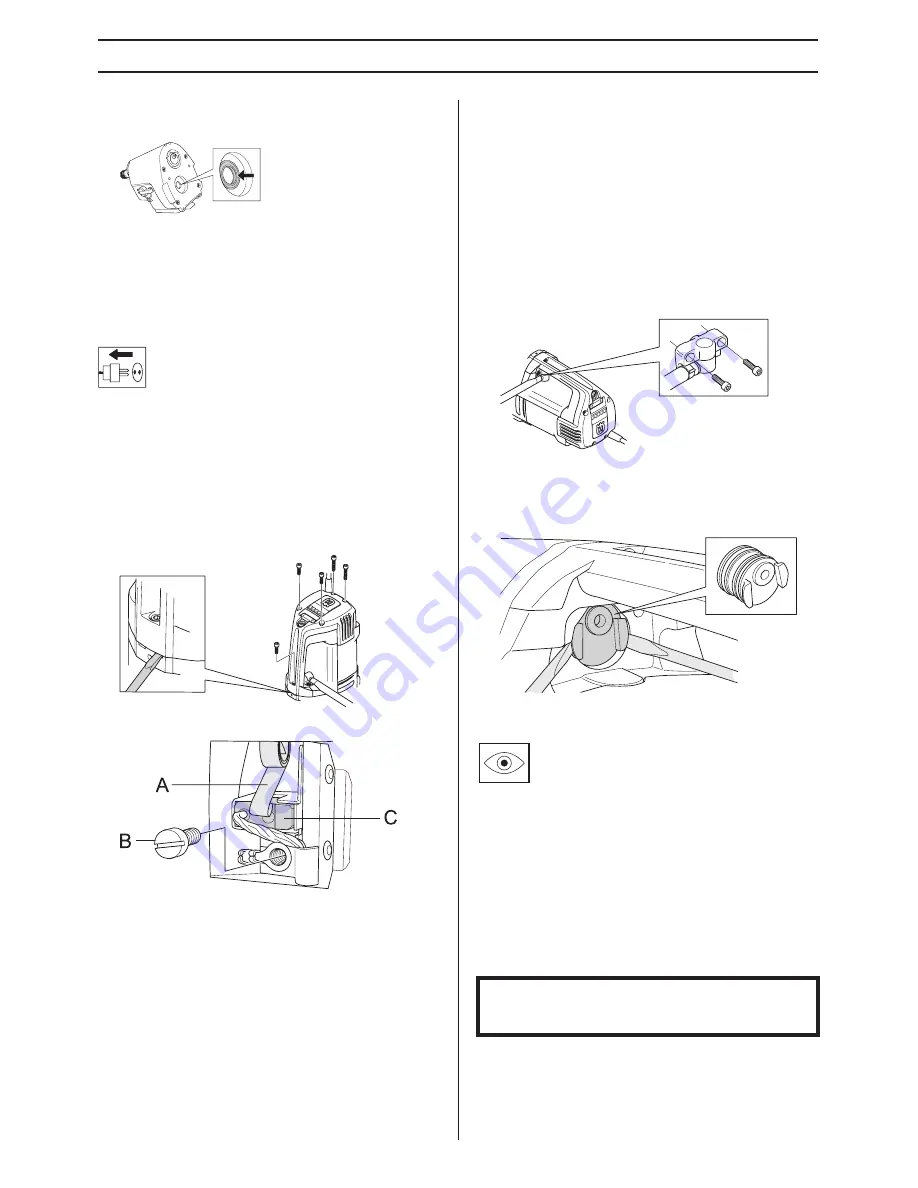
1

Remove the 5 screws from the inspection cover. Use a 
chisel in the break tracks to easier remove the inspection 
cover.

2

Lift the carbon brush holder spring to one side (A).

3

Loosen the screw (B).

4

Pull out the carbon brush connector.

5

Pull the carbon brush out from the holder (C).

6

Clean the brush holder with compressed air or a brush. 
Replace the brush if worn. 

7

Fit the new carbon brush. Make sure that the side with the 
copper wire is facing the gear box and that the carbon 
brush slides easily in the brush retainer. If the carbon 
brush is fitted in the wrong direction it can get jammed.

8

Put the brush holder spring back into place.

9

Insert the carbon brush connection under the screw.

10 Repeat the procedure with the other carbon brush.

11 Guide the inspection cover into the handle's tracks.  Begin 

with the screw at the very bottom of the handle and 
unscrew the inspection cover's five screws. 

12 Let the machine idle for 10 minutes to run in the new 

carbon brushes.

Replacing the seal retainer

If there is oil or water coming out of the leakage hole the seal 
retainer must be replaced. 

1

Loosen the two screws for the water module. 

2

Use two flathead screwdrivers to carefully prize open the 
seal retainer.

3

Carefully push in the new seal retainer and screw the 
water module back on. 

Daily maintenance

1

Check that nuts and screws are tight.

2

Check that the power switch unit works smoothly.

3

Clean the outside of the machine.

4

Check and clean the cooling air openings.

5

Check that the cord and extension cord are intact and in 
good condition.

Repairs

Important All types of repairs may only be carried out by 
authorised repairmen. This is so that the operators are not 
exposed to great risks.

Summary of Contents for 1152417-30

Page 1: ...before using the machine Manual de instrucciones Lea detenidamente el manual de instrucciones y asegúrese de entender su contenido antes de utilizar la máquina Instruções para o uso Leia as instruções para o uso com toda a atenção e compreenda o seu conteúdo antes de fazer uso da máquina ËÁ Â Ú Ûˆ È ß ÛÙ ÚÔÛÂÎÙÈÎ ÙÈ ËÁ Â Ú Ûˆ Î È Î Ù ÓÔ ÛÙ ÙÔ ÂÚÈ fiÌÂÓÔ ÚÈÓ ÚËÛÈÌÔ ÔÈ ÛÂÙ ÙÔ ÌË ÓËÌ ...

Page 2: ...ctrical and electronic equipment By ensuring that this product is taken care of correctly you can help to counteract the potential negative impact on the environment and people that can otherwise result through the incorrect waste management of this product For more detailed information about recycling this product contact your municipality your domestic waste service or the shop from where you pu...

Page 3: ...ine 6 Personal protective equipment 6 General safety precautions 7 General working instructions 8 Machine s safety equipment 9 STARTING AND STOPPING Before starting 10 Starting 10 Stopping 10 MAINTENANCE General 11 Changing the drill bit 11 Cleaning 11 Electrical Feed 11 Changing the gearbox oil 11 Replacing the carbon brushes 12 Replacing the seal retainer 12 Daily maintenance 12 Repairs 12 TECHN...

Page 4: ...equipped with LEDs which indicate the power output This way you can always get maximum power output without damaging the machine The drilling machine is equipped with SoftstartTM SmartstartTM ElgardTM and speed control SoftstartTM SoftstartTM is an electronic current limiter which provides a softer start Maximum speed is reached about three seconds after the machine is turned on SmartstartTM If th...

Page 5: ... Quick mount for Husqvarna stand 6 Water connector 7 LEDs for indicating power output 8 Switch 9 SmartstartTM 10 Inspection cover 11 Leakage hole 12 Inspection hatch 13 Junction coupling accessory 14 Adapter accessory 15 Ground fault circuit interrupter not for GB 16 Open ended spanner 32 mm 17 Engine mount stand 18 Operator s manual ...

Page 6: ...olicy of continuous product development Husqvarna reserves the right to modify the design and appearance of products without prior notice and without further obligation introduce design modifications All information and all data in the Operator s Manual were applicable at the time the Operator s Manual was sent to print Personal protective equipment Protective helmet Hearing protection Protective ...

Page 7: ...ool to rain Water entering a power tool will increase the risk of electric shock Ensure the cord is behind you when you start to use the machine so that the cord will not be damaged Personal safety Wear personal protective equipment See instructions under the heading Personal protective equipment Never use the machine if you are tired if you have drunk alcohol or if you are taking medication that ...

Page 8: ...ine and stand in dry and frost free conditions General working instructions The machine has a very high torque This demands good concentration during work as serious personal injuries can occur if the drill bit suddenly jams Keep your hands at a safe distance from the drill spindle and drill bit when the machine is running Keep an eye open for oil or water leakage If water or oil trickles out from...

Page 9: ... switch Switch the on off switch off to stop the machine A defective power switch should be replaced by an authorized service workshop WARNING Never use a machine that has faulty safety equipment IMPORTANT All servicing and repair work on the machine requires special training This is especially true of the machine s safety equipment If your machine fails any of the checks described below you must ...

Page 10: ...the working speed by turning the drill spindle and at the same time move the gear knob to the required position 2 Turn on the water cooling 3 Start the machine by switching on the on off switch Also press if desired the SmartstartTM button Stopping Switch the on off switch off to stop the machine Cooling Run the machine unloaded for a minute or two to cool the motor WARNING Note the following befo...

Page 11: ...clear and clean Use compressed air to periodically clean the motor Remove the inspection cover and clean the cover Electrical Feed Check that the cord and extension cord are intact and in good condition Never use the machine if the cord is damaged hand it in to an authorized service workshop for repair Changing the gearbox oil Contact your dealer to get the right oil The oil in the gearbox must be...

Page 12: ...facing the gear box and that the carbon brush slides easily in the brush retainer If the carbon brush is fitted in the wrong direction it can get jammed 8 Put the brush holder spring back into place 9 Insert the carbon brush connection under the screw 10 Repeat the procedure with the other carbon brush 11 Guide the inspection cover into the handle s tracks Begin with the screw at the very bottom o...

Page 13: ...ter connector G 1 4 Water pressure max bar 8 Noise emissions Sound power level measured EN 12348 2000 dB A 97 Sound levels Noise pressure level at the operators ear measured according to EN 12348 2000 dB A 88 Gear housing Drill bit speed with load rpm Drill bit load without load rpm Recommended drill bit size mm Recommended drill bit size inch 1 240 310 200 400 8 16 2 530 690 100 200 4 8 3 915 119...

Page 14: ...ith the requirements of the COUNCIL S DIRECTIVE of June 22 1998 relating to machinery 98 37 EC annex IIA of December 15 2004 relating to electromagnetic compatibility 2004 108 EC of December 12 2006 relating to electrical equipment 2006 95 EC The following standards have been applied SS EN ISO 12100 2003 EN55014 1 2006 EN55014 2 1997 A1 EN61000 3 2 2006 EN61000 3 3 1995 A1 A2 EN12348 2000 The supp...

Page 15: ...English 15 WIRING DIAGRAM ...

Page 16: ... z TIi 0G 2009 04 15 z TIi 0G 1152417 30 ...

Reviews: