background image

www.usa.husqvarna.com

Operator Safety

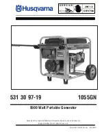
Equipment Description

  Read this manual carefully and become familiar 

with your generator. Know its applications, its 

limitations and any hazards involved.

The generator is an engine–driven, revolving field, 

alternating current (AC) generator. It was designed to supply 

electrical power for operating compatible electrical lighting, 

appliances, tools and motor loads. The generator’s revolving 

field is driven at about 3,600 rpm by a single-cylinder 

engine.

NOTICE

Exceeding generators wattage/amperage capacity can 

damage generator and/or electrical devices connected to 

it.

•  DO NOT exceed the generator’s wattage/amperage capacity. 

See 

Don’t Overload Generator

 in the 

Operation

 section.

Every effort has been made to ensure that the information 

in this manual is both accurate and current. However, the 

manufacturer reserves the right to change, alter or otherwise 

improve the generator and this documentation at any time 

without prior notice.
The Emission Control System for this generator is warranted 

for standards set by the Environmental Protection Agency 

and the California Air Resources Board.

Safety Rules

   This is the safety alert symbol. It is used to alert 

you to potential personal injury hazards. Obey all 

safety messages that follow this symbol to avoid 

possible injury or death.

The safety alert symbol ( ) is used with a signal word 

(

DANGER, WARNING, CAUTION

), a pictorial and/or a safety 

message to alert you to hazards. 

DANGER

 indicates a hazard 

which, if not avoided, 

will

 result in death or serious injury. 

WARNING

 indicates a hazard which, if not avoided, 

could


result in death or serious injury. 

CAUTION

 indicates a hazard 

which, if not avoided, 

might

 result in minor or moderate 

injury. 

NOTICE

 indicates a situation that could result in 

equipment damage. Follow safety messages to avoid or 

reduce the risk of injury or death.
The manufacturer cannot possibly anticipate every possible 

circumstance that might involve a hazard. The warnings in 

this manual, and the tags and decals affixed to the unit are, 

therefore, not all-inclusive. If you use a procedure, work 

method or operating technique that the manufacturer does 

not specifically recommend, you must satisfy yourself that 

it is safe for you and others. You must also make sure that 

the procedure, work method or operating technique that you 

choose does not render the generator unsafe.

Hazard Symbols and Meanings

A - Explosion 

F - Hot Surface 

B - Fire 

G - Flying Objects 

C - Electric Shock 

H - Moving Parts 

D - Toxic Fumes 

J - Read Manual 

E - Kickback


WARNING

Running engine gives off carbon monoxide, an 

odorless, colorless, poison gas.
Breathing carbon monoxide can cause 

headache, fatigue, dizziness, vomiting, 

confusion, seizures, nausea, fainting or death.

•  Operate generator ONLY outdoors.
•  Install a battery operated carbon monoxide alarm near the 

bedrooms.

•  Keep exhaust gas from entering a confined area through 

windows, doors, ventilation intakes, or other openings.

•  DO NOT start or run engine indoors or in an enclosed area, 

(even if windows and doors are open), including the generator 

compartment of a recreational vehicle (RV).

A

B

C

D

G

E

F

H

J

Summary of Contents for 1055 GN

Page 1: ...904 2007 12 Manual No 204839A Revision 08 25 2007 531 30 97 19 1055GN 5500 Watt Portable Generator Husqvarna is a registered trademark of Husqvarna AB and is used under license to Briggs Stratton Power Products Group LLC ...

Page 2: ...assembly before use Refer to the Assembly section of this manual for instructions on final assembly procedures Follow the instructions completely Where to Find Us You never have to look far to find Briggs Stratton support and service for your generator Consult your Yellow Pages There are over 30 000 Briggs Stratton authorized service dealers worldwide who provide quality service You can also conta...

Page 3: ...es and Controls 10 Cord Sets and Receptacles 11 Operation 12 Starting the Engine 12 Connecting Electrical Loads 13 Stopping the Engine 13 Don t Overload Generator 14 Maintenance 15 Maintenance Schedule 15 Generator Maintenance 15 Fuel Valve Maintenance 16 Engine Maintenance 16 Storage 19 Troubleshooting 20 Warranties 21 Emissions Control System Warranty 21 Generator Owner Warranty 23 Specification...

Page 4: ...rds DANGER indicates a hazard which if not avoided will result in death or serious injury WARNING indicates a hazard which if not avoided could result in death or serious injury CAUTION indicates a hazard which if not avoided might result in minor or moderate injury NOTICE indicates a situation that could result in equipment damage Follow safety messages to avoid or reduce the risk of injury or de...

Page 5: ...stop engine with electrical devices plugged in and turned on warning Fuel and its vapors are extremely flammable and explosive Fire or explosion can cause severe burns or death WHEN ADDING OR DRAINING FUEL Turn generator OFF and let it cool at least 2 minutes before removing fuel cap Loosen cap slowly to relieve pressure in tank Fill or drain fuel tank outdoors DO NOT overfill tank Allow space for...

Page 6: ...wire where it cannot contact spark plug WHEN TESTING FOR ENGINE SPARK Use approved spark plug tester DO NOT check for spark with spark plug removed caution Excessively high operating speeds increase risk of injury and damage to generator Excessively low speeds impose a heavy load DO NOT tamper with governed speed Generator supplies correct rated frequency and voltage when running at governed speed...

Page 7: ...so that engine end is up 2 Slide axle A through both mounting brackets 3 Slide a wheel B over axle NOTE Be sure to install wheel with raised hub inboard 4 Place a washer C on axle and then place an e ring D in axle groove caution E rings can cause eye injury E rings can spring back and become airborne when installing or removing Always wear eye protection when installing removing e rings 5 Install...

Page 8: ...ter using fuel switch to a different fuel provider or change brands This engine is certified to operate on gasoline The emission control system for this engine is EM Engine Modifications warning Fuel and its vapors are extremely flammable and explosive Fire or explosion can cause severe burns or death WHEN ADDING FUEL Turn generator OFF and let it cool at least 2 minutes before removing fuel cap L...

Page 9: ...ctric utility workers due to backfeed of electrical energy When using generator for backup power notify utility company Use approved transfer equipment to isolate generator from electric utility Use a ground fault circuit interrupter GFCI in any damp or highly conductive area such as metal decking or steel work DO NOT touch bare wires or receptacles DO NOT use generator with electrical cords which...

Page 10: ...ease have these readily available when calling for assistance G Choke Lever Used when starting a cold engine H Air Cleaner Protects engine by filtering dust and debris out of intake air J Recoil Starter Used to start the engine K Oil Drain Plug Drain engine oil here L Rocker Switch Set this switch to On before using recoil starter Set switch to Off to stop engine M Oil Fill Cap Check and fill engi...

Page 11: ... 30 Amp Locking Receptacle Use a NEMA L14 30 plug with this receptacle Connect a 4 wire cord set rated for 250 Volt AC loads at 30 Amps or greater You can use the same 4 wire cord if you plan to run a 120 Volt load This receptacle powers 120 240 Volt AC 60 Hz single phase loads requiring up to 5 500 watts of power 5 5 kW at 22 9 Amps for 240 Volts or two independent 120 Volt loads at 22 9 Amps eac...

Page 12: ...o Run position and pull the handle repeatedly until the engine starts 6 Move choke lever to Run position a short distance at a time over several seconds in warm weather or minutes in cold weather Let engine run smoothly before each change Operate with choke in Run position warning Contact with muffler area can result in serious burns Exhaust heat gases can ignite combustibles structures or damage ...

Page 13: ... amperage capacity See Don t Overload Generator in the Operation section Start generator and let engine stabilize before connecting electrical loads Connect electrical loads in OFF position then turn ON for operation Turn electrical loads OFF and disconnect from generator before stopping generator Stopping the Engine 1 Turn OFF and unplug all electrical loads from generator panel receptacles NEVER...

Page 14: ...rator power is to sequentially add loads as follows 1 With nothing connected to the generator start the engine as described in this manual 2 Plug in and turn on the first load preferably the largest load you have 3 Permit the generator output to stabilize engine runs smoothly and attached device operates properly 4 Plug in and turn on the next load 5 Again permit the generator to stabilize 6 Repea...

Page 15: ...blishment or individual However to obtain no charge emissions control service the work must be performed by a factory authorized dealer See the Emissions Warranty Generator Maintenance Generator maintenance consists of keeping the unit clean and dry Operate and store the unit in a clean dry environment where it will not be exposed to excessive dust dirt moisture or any corrosive vapors Cooling air...

Page 16: ...ils for best performance Other high quality detergent oils are acceptable if classified for service SF SG SH SJ or higher DO NOT use special additives Outdoor temperatures determine the proper oil viscosity for the engine Use the chart to select the best viscosity for the outdoor temperature range expected Below 40 F 4 C the use of SAE 30 will result in hard starting Above 80 F 27 C the use of 10W...

Page 17: ...y air cleaner Replace the air cleaner every 25 hours of operation or once each year whichever comes first Replace more often if operating under dirty or dusty conditions To service the air cleaner follow these steps 1 Loosen screws D and remove air cleaner cover E 2 Carefully remove cartridge F from base G 3 Install clean or new air cleaner assembly inside cover Dispose of old filter properly 4 As...

Page 18: ...tach screen and muffler guard Air Cooling System Over time debris may accumulate in cylinder cooling fins and cannot be observed without partial engine disassembly For this reason we recommend you have an authorized Briggs Stratton service dealer clean the cooling system D per recommended intervals see Maintenance Schedule in beginning of Maintenance section Equally important is to keep top of eng...

Page 19: ...n cause severe burns or death WHEN STORING FUEL OR EQUIPMENT WITH FUEL IN TANK Store away from furnaces stoves water heaters clothes dryers or other appliances that have pilot light or other ignition source because they can ignite fuel vapors WHEN DRAINING FUEL Turn generator OFF and let it cool at least 2 minutes before removing fuel cap Loosen cap slowly to relieve pressure in tank Drain fuel ta...

Page 20: ... set to Off 2 Fuel Valve is in Off position 3 Dirty air cleaner 4 Out of fuel 5 Stale fuel 6 Spark plug wire not connected to spark plug 7 Bad spark plug 8 Water in fuel 9 Flooded 10 Excessively rich fuel mixture 11 Intake valve stuck open or closed 12 Engine has lost compression 1 Set switch to On 2 Turn fuel valve to Open position 3 Clean or replace air cleaner 4 Fill fuel tank 5 Drain fuel tank...

Page 21: ...your Operating and Maintenance Instructions B S recommends that you retain all your receipts covering maintenance on your small off road engine but B S cannot deny warranty solely for the lack of receipts or for your failure to ensure the performance of all scheduled maintenance As the small off road engine owner you should however be aware that B S may deny you warranty coverage if your small off...

Page 22: ... any maintenance or repairs The owner is responsible for the performance of all required maintenance as defined in the B S Operator s Manual 6 Consequential Coverage Coverage hereunder shall extend to the failure of any engine components caused by the failure of any Warranted Part still under warranty Emission Information Engines that are certified to meet the California Air Resources Board CARB E...

Page 23: ...r and apologize to you for being inconvenienced Any Authorized Service Dealer may perform warranty repairs Most warranty repairs are handled routinely but sometimes requests for warranty service may not be appropriate For example warranty service would not apply if equipment damage occurred because of misuse lack of routine maintenance shipping handling warehousing or improper installation Similar...

Page 24: ...nce with SAE J1995 Revision 2002 05 Torque values are derived at 3060 RPM horsepower values are derived at 3600 RPM Actual gross engine power will be lower and is affected by among other things ambient operating conditions and engine to engine variability Given both the wide array of products on which engines are placed and the variety of environmental issues applicable to operating the equipment ...

Page 25: ...qvarna com Copyright 2007 Briggs Stratton Power Products Group LLC All rights reserved No part of this material may be reproduced or transmitted in any form by any means without the express written permission of Briggs Stratton Power Products Group LLC ...

Page 26: ...ic with Cap 35 791745 KIT Hose Fuel cut to fit 36 192376GS SCREW 12 24 x 1 2 Thread Forming 37 56893GS CRIMPTITE 10 24 x 1 2 38 B2153GS SCREW Self Driller 12 14 x 7 8 40 199256GS BOLT Shoulder M6 1 0 w washer 41 192980GS VALVE Fuel 44 202954GS ASSY Tank Fuel Includes Items 41 50 51 52 53 55 56 Item Part Description 45 189135GS CAP Tank 48 195373GS WIRE Ground 50 188333GS DECAL Instruction Fuel Lev...

Page 27: ...Rear Cover 4 NUT Palnut Pushnut 3 16 5 43437GS OUTLET 120 240 Locking 30A 6 68759GS OUTLET 120V 20Amp Duplex 7 NUT Palnut Pushnut 5 32 8 202029GS BREAKER 20 2P 9 192241GS SCREW Tapping 3 5 x 14 10 22694GS HOUSING Receptacle 11 82308GS SCREW Tapping STC 3 x 18 Items without part numbers are common fasteners and are available at your local hardware store 4 www usa husqvarna com ...

Page 28: ...ernator 2 190032GS ROTOR 3 190079AGS STATOR 4 186060GS RBC with O Ring p n 189197GS 5 86308HGS HHCS M6 1 0 x 140 SEMS 6 91825GS ASSEMBLY Holder Rectifier Brush 7 66849GS TAPTITE M5 0 8 x 16 8 22694GS RECEPTACLE 6 pin 9 81917GS PIN Roll 4mm x 10 10 193428AGS WIRE A Ground 13 194274GS HARNESS Wire Power 14 65791GS BEARING 5 ...

Page 29: ...ange Serrated 7 203977GS ASSY Support 8 198669GS GRIP 9 B193200GS ASSY Handle w Grip 10 NUT M8 1 25 Nylok 11 B4135GS PIN Handle Item Part Description 12 WASHER 1 2 x 0 346 x 0 03 Nylon 13 HHCS M8 1 25 x 45 14 WASHER Flat 5 16 M8 Items Not Illustrated 203979GS SUBKIT Hardware Items without part numbers are common fasteners and are available at your local hardware store 6 www usa husqvarna com ...

Reviews: