background image

26

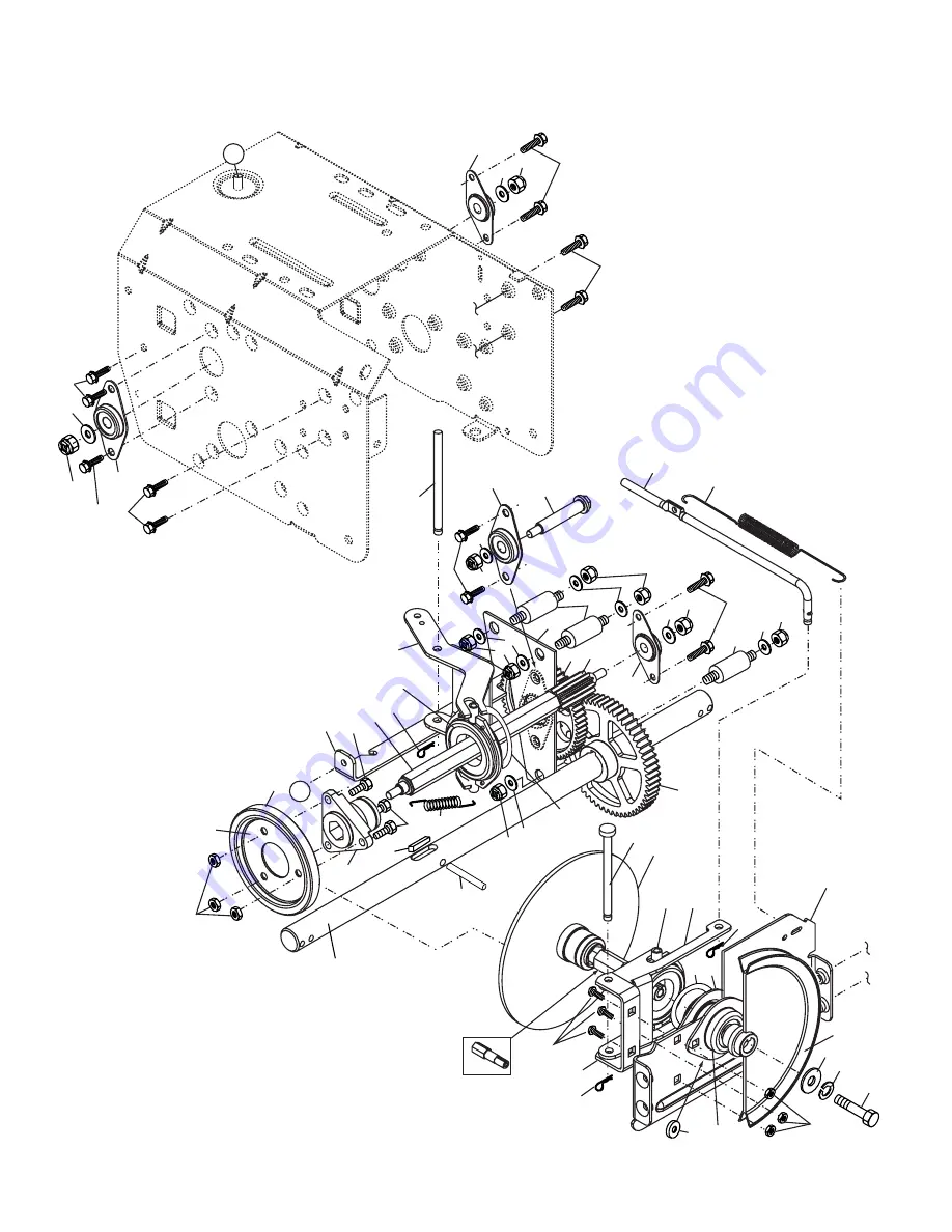
REPAIR PARTS

                                                                                                 DRIVE

SNOW THROWER - - MODEL NO. 1027STE (HL1027STEA), PRODUCT NO. 954 63 35-45

35

33

15

41

22

34

29

22

31

26

7

2

43

2

11

3

3

25

24

23

12

32

27

44

20

21

21

22

16

1

17

15

2

1

4

13

4

1

2

5

3

4

2

5

3

3

5

1

2

3

13

1

5

2

7

8

9 10

6

3

3

41

14

2

19

18

28

30

40

39

38

36

37

33

Summary of Contents for 1027STE

Page 1: ...1027STE Owner s Manual ...

Page 2: ...nt on a trailer with a portable container rather than from a gasoline dispenser nozzle Keep the nozzle in contact with the rim of the fuel tankopeningatalltimes untilrefuelingiscomplete Do not use a nozzle lock open device If fuel is spilled on clothing change clothing im mediately For all units with electric starting motors use electric starting extension cords certified CSA UL Use only with a re...

Page 3: ...edy please contact your nearest authorized service center department We have competent well trained tech nicians and the proper tools to service or repair this unit Please read and retain this manual The instructions will enable you to assemble and maintain your snow thrower properly Always observe the SAFETY RULES SERIAL NUMBER ___________________________ DATE OF PURCHASE _______________________ ...

Page 4: ...NTENANCE 14 15 MAINTENANCE SCHEDULE 14 SERVICE AND ADJUSTMENTS 16 18 STORAGE 18 TROUBLESHOOTING 19 REPAIR PARTS 20 31 SAFETY RULES 2 3 PRODUCT SPECIFICATIONS 3 CUSTOMER RESPONSIBILITIES 3 WARRANTY 32 ASSEMBLY PRE OPERATION 5 7 OPERATION 8 13 ...

Page 5: ... packing materials except plastic tie holding speed control rod to lower handle 4 Remove snow thrower from carton and check carton thoroughly for additional loose parts HOW TO SET UP YOUR SNOW THROWER TOOL BOX See Fig 8 A toolbox is provided on your snow thrower The toolbox is located on top of the belt cover Store the extra shear bolts nuts and multi wrench provided in parts bag in the toolbox NO...

Page 6: ...TRACTION DRIVE CONTROL LEVER INSTALL TRACTION DRIVE CONTROL ROD See Figs 3 and 4 The traction drive control rod has the long loop on the end of the spring as shown 1 Slide rubber sleeve up rod and hook end of spring into pivot bracket with loop opening down as shown 2 With top end of rod positioned under left side of control panel push rod down and insert top end of rod into hole in drive control ...

Page 7: ...ead 1 Place discharge chute assembly on top of chute base with discharge opening toward front of snow thrower 2 Position chute rotater head over chute bracket If nec essary rotate chute assembly to align square and pin on underside of chute rotater head with holes in chute bracket 3 With chute rotater head and chute bracket aligned position chute rotater head on pin and threaded stud of mounting b...

Page 8: ... Save this manual for future reference These symbols may appear on your snow thrower or in literature supplied with the product Learn and understand their meaning FORWARD PRIMER IGNITION KEY INSERT TO START AND RUN PULL OUT TO STOP READ AND FOLLOW ALL SAFETY INFORMATION AND INSTRUCTIONS BEFORE USE OF THIS PRODUCT KEEP THESE INSTRUCTIONS FOR FUTURE REFERENCE DANGER OR WARNING REVERSE SNOW DISCHARGE...

Page 9: ... handle used for starting the engine Primer pumps additional fuel from the carburetor to the cylinder for use when starting a cold engine Throttle engine control used to select either FAST or SLOW engine speed and to STOP the engine MEETS A N S I SAFETY REQUIREMENTS Our snow throwers conform to the standards of the American National Standards Institute FIG 8 TRACTION DRIVE CONTROL LEVER DISCHARGE ...

Page 10: ...peration clear of all persons small children and pets at all times including startup WARNING If the discharge chute or auger become clogged shut off en gine and wait for all moving parts to stop Use a stick NOT YOUR HANDS to unclog the chute and or auger The DIRECTION in which snow is to be thrown is controlled by the discharge chute control lever To change the discharge chute position press down ...

Page 11: ...drive speed control lever Press downward on the speed control lever and move lever to desired position BEFORE engaging the trac tion drive control lever Be sure lever springs back and locks into desired position CAUTION Do not move speed control lever when traction drive control lever is engaged Damage to the snow thrower can result Slower speeds are for heavier snow and faster speeds are for ligh...

Page 12: ...ucts in the fuel tank or permanent damage may occur SKID PLATE LOW POSITION HIGH GROUND CLEARANCE 1 2 HEX NUT HIGH POSITION LOW GROUND CLEARANCE AUGER HOUSING SCRAPER BAR The scraper bar is not adjustable but is reversible After considerable use it may become worn When it has worn almost to the edge of the housing it can be reversed providing additional service before requiring replacement Replace...

Page 13: ...engine To avoid possible freeze up of the starter proceed as fol lows OPERATION ELECTRIC STARTER 1 Connect the power cord to the engine 2 Plug the other end of the power cord into a three hole grounded 120 Volt A C receptacle 3 While the engine is running push starter button and spin the starter for several seconds NOTE The unusual sound made while starter is spinning will not harm the engine or s...

Page 14: ...his manual NOTE Use only Original Equipment Manufacturer OEM parts to service this unit Failure to do so can cause the unit to malfunction and pose a risk of injury to the operator BEFORE EACH USE 1 Check engine oil level 2 Check for loose fasteners 3 Check controls to be sure they are functioning properly LUBRICATION Keep your snow thrower well lubricated See LUBRICATION CHART SAE 30 Motor Oil Se...

Page 15: ...ntact with spark plug 2 Clean area around drain plug 3 Remove drain plug and drain oil in a suitable container 4 Install drain plug and tighten securely 5 Wipe off any spilled oil from snow thrower and engine 6 Install left wheel if removed for draining oil Be sure to install klick pin into proper hole in wheel axle See TO REMOVE WHEELS in the Service and Adjustments section of this manual 7 Remov...

Page 16: ... To replace the shear bolts 1 Disengage all controls and move throttle control to STOP position Wait for all moving parts to stop 2 Disconnect spark plug wire from spark plug and place it wear it cannot come in contact with spark plug 3 Align hole in auger hub with hole in auger shaft and install a new 1 4 20 x 2 shoulder shear bolt Install 1 4 20 lock nut and tighten securely CAUTION Do not subst...

Page 17: ...inging snow thrower together separate the snow thrower and repeat step 10 Belt must be fully seated in pulley groove when bringing the snow thrower together 12 Install the two 2 hex bolts and lock washers and tighten securely 13 INSTALLENGINEPULLEY Placebeltinpulleygroove and slide pulley on crankshaft Install flat washer lock washer and bolt and tighten securely 30 35 ft lbs torque Make sure belt...

Page 18: ...each the carburetor Do not empty the gas tank and carburetor if using fuel stabilizer ENGINE OIL Drain oil with engine warm and replace with clean en gine oil See ENGINE in the Maintenance section of this manual CYLINDER 1 Remove spark plug 2 Pour one ounce 29 ml of oil through spark plug hole into cylinder 3 Pull recoil starter handle slowly a few times to distribute oil 4 Replace with new spark ...

Page 19: ...s in FULL position 1 Move choke to OFF position runs roughly 2 Blockage in fuel line 2 Clean fuel line 3 Stale fuel 3 Empty fuel tank carburetor refill with fresh clean gasoline 4 Water in fuel 4 Empty fuel tank carburetor refill with fresh clean gasoline 5 Carburetor is in need of 5 Contact a qualified service center adjustment or overhaul Excessive 1 Loose parts or damaged 1 Tighten all fastener...

Page 20: ...ER MODEL NO 1027STE HL1027STEA PRODUCT NO 954 63 35 45 22 18 21 2 19 6 6 5 6 6 9 12 7 7 8 6 11 27 27 30 26 25 24 23 20 31 25 24 26 23 29 21 2 19 20 18 10 13 4 14 16 15 36 37 50 47 42 44 27 43 46 38 45 27 43 42 41 40 39 34 32 49 19 48 51 33 35 28 19 55 28 19 55 ...

Page 21: ...46 97 Washer Thrust 1 28 532 18 17 94 Bolt Shear 29 532 18 40 93 Skid Plate LH 30 532 18 41 03 Auger Assembly RH 31 532 18 41 00 Auger Assembly LH 32 532 17 46 99 O Ring 33 532 17 47 00 Bushing Flange 3 4 34 532 17 46 81 Washer Thrust 3 4 35 532 17 46 84 Bearing Thrust 3 4 36 532 17 46 60 Shaft Impeller 37 532 17 46 83 Washer Thrust 5 8 38 532 17 46 86 Bushing Flange 5 8 39 532 15 00 78 Screw Hex ...

Page 22: ...EPAIR PARTS CONTROL PANEL DISCHARGE CHUTE SNOW THROWER MODEL NO 1027STE HL1027STEA PRODUCT NO 954 63 35 45 1 2 6 7 4 5 6 8 8 19 2 2 30 26 28 27 27 25 20 29 24 18 13 14 3 11 12 21 9 14 16 17 15 10 Chute knob ...

Page 23: ...Nylon 15 532 18 41 12 Chute Assembly 16 532 18 41 13 Deflector Assembly 17 532 17 91 45 Seal Deflector 18 532 12 84 15 Rivet Blind 19 532 18 33 33 Knob Speed Control Lever 20 872 27 05 06 Bolt Carriage 5 16 18 x 3 4 21 532 15 54 15 Washer Flat 5 16 24 874 78 05 28 Screw Hex Head 5 16 18 x 1 3 4 25 532 15 53 77 Nut Lock 5 16 18 26 532 17 92 57 Lever Assembly Speed Control 27 532 16 96 75 Retainer H...

Page 24: ... SNOW THROWER MODEL NO 1027STE HL1027STEA PRODUCT NO 954 63 35 45 5 11 12 15 7 10 33 18 19 37 34 35 20 20 21 21 6 11 5 36 13 2 5 15 11 4 4 3 3 16 17 16 23 22 38 39 24 27 26 24 25 27 40 22 17 1 4 4 14 5 8 6 28 9 32 30 31 31 32 ...

Page 25: ... Rod Traction Control 20 532 18 04 28 End Control Rod 21 873 35 05 00 Nut Hex Jam 5 16 18 22 872 12 06 18 Bolt Carriage 3 8 16 x 2 1 4 23 532 18 40 88 Handle Tube Lower 24 532 18 04 47 Sleeve Spring 25 532 18 09 26 Spring Traction Drive 26 532 17 86 69 Spring Auger Control 27 871 21 06 16 Screw Hex Head 3 8 16 x 1 28 532 18 04 94 Clip Panel 30 532 18 33 46 Console Panel 31 532 17 52 62 Screw Hex H...

Page 26: ...DEL NO 1027STE HL1027STEA PRODUCT NO 954 63 35 45 35 33 15 41 22 34 29 22 31 26 7 2 43 2 11 3 3 25 24 23 12 32 27 44 20 21 21 22 16 1 17 15 2 1 4 13 4 1 2 5 3 4 2 5 3 3 5 1 2 3 13 1 5 2 7 8 9 10 6 3 3 41 14 2 19 18 28 30 40 39 38 36 37 33 ...

Page 27: ...Hex Head 5 16 18 x 7 8 22 532 08 51 79 Retainer Hairpin 23 532 18 01 35 Spring Bias 24 532 18 00 81 Gear Axle 58 Teeth 25 532 17 86 95 Pin Pivot Lever 26 532 17 53 41 Plate Assembly Drive 27 532 17 93 52 Shaft Axle 28 532 17 53 40 Shaft Short Hex 29 532 18 40 77 Lever Shifter Plate 30 532 18 40 76 Bracket Shifter Support 31 872 27 05 05 Bolt Carriage 5 16 18 x 5 8 32 532 17 88 79 Key Square 1 4 x ...

Page 28: ...ER MODEL NO 1027STE HL1027STEA PRODUCT NO 954 63 35 45 10 21 6 19 17 10 21 22 23 2 1 3 4 6 7 8 9 12 13 15 27 26 25 24 18 7 6 20 14 28 6 30 29 31 31 47 48 46 40 44 26 11 49 50 51 52 35 34 33 32 38 36 41 6 37 39 42 43 11 53 54 11 44 45 26 16 41 41 11 5 ...

Page 29: ...8 26 532 85 02 63 Washer Lock 3 8 27 532 85 10 84 Screw Hex Head 3 8 24 x 1 3 8 28 532 18 35 61 Guide Belt 29 532 18 04 65 Cover Belt 30 532 17 88 30 Cover Toolbox 31 817 49 04 08 Screw Hex Head 1 4 20 x 1 2 32 532 17 92 56 Bolt Shoulder 5 16 18 33 532 18 78 53 Bellcrank Shifter 34 532 18 04 01 Screw Hex Head 1 4 28 x 3 4 35 532 17 92 40 Arm Auger Control 36 873 80 05 00 Nut Lock 5 16 18 37 532 18...

Page 30: ...30 REPAIR PARTS WHEELS DECALS SNOW THROWER MODEL NO 1027STE HL1027STEA PRODUCT NO 954 63 35 45 3 2 4 4 5 5 6 6 4 4 1 2 5 3 1 4 2 1 10 7 6 8 9 10 ...

Page 31: ...N 1 532 18 10 38 Decal Danger 2 532 18 79 11 Decal Husqvarna 3 532 18 10 34 Decal Danger Deflector 4 532 18 10 41 Decal Danger 5 532 18 75 86 Decal Husqvarna 1027STE 6 532 18 10 32 Decal Instruction 7 532 15 57 98 Decal Traction Lever 8 532 15 58 00 Decal Auger Lever 9 532 18 10 36 Decal Speed Control 10 532 15 57 94 Decal Husqvarna Crown 532 18 78 26 Owner s Manual NOTE All component dimensions g...

Page 32: ... information supplied at the time of pur chase all claims must be sent to the appropriate manufacturer 4 Lawn and garden attachments are covered by a third party which gives a warranty all claims for war ranty should be sent to the manufacturer and 5 Emission Control System components necessary to comply with CARB TIER II and EPA regulations which are manufactured by third party engine manufacture...

Reviews: