background image

 
 12 

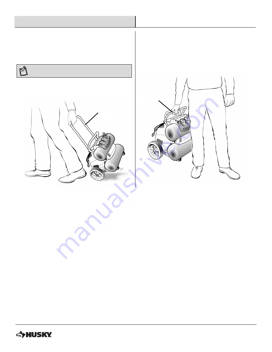
Transport and Lifting 


1


Transport 

2


Lifting 


Pull the telescopic handle (D) out until it locks into place. 


NOTE

: This handle is only for pulling the unit.  

DO NOT lift the unit by this handle.


To lower handle push it down. 


For lifting the unit use only the black carry handle (A). 


A

Summary of Contents for H1504ST2

Page 1: ...ually create quality products designed to enhance your home Visit us online to see our full line of products available for your home improvement needs Thank you for choosing Husky USE AND CARE GUIDE 4...

Page 2: ...are and Cleaning 15 Troubleshooting 16 Service Parts 18 Parts diagram 18 Parts list 19 Symbols 20 Glossary 21 Safety Information PRODUCT FOR CONSUMER USE ONLY Not intended for commercial use DANGER Th...

Page 3: ...product until you read thoroughly and understand completely the operator s manual Save this operator s manual and review frequently for continuing safe operation and instructing others who may use th...

Page 4: ...this rule will reduce the risk of deterioration of the enclosure plastic SERVICE 1 Tool service must be performed only by qualified repair personnel Service or maintenance performed by unqualified pe...

Page 5: ...periodically and if damaged have repaired at your nearest Authorized Service Center Constantly stay aware of cord location Following this rule will reduce the risk of electric shock or fire 22 Never...

Page 6: ...pressor with a damaged cord since touching the damaged area could cause electrical shock resulting in serious personal injury 4 When working with the air compressor outdoors use an extension cord that...

Page 7: ...nductor with insulation having an outer surface that is green with or without yellow stripes is the equipment grounding conductor If repair or replacement of the electric cord or plug is necessary do...

Page 8: ...er normal wear and tear or any malfunction failure or defect resulting from misuse abuse neglect alteration modification or repair by other than a service center authorized to repair HUSKY branded air...

Page 9: ...4 2 SCFM 40 PSI Lubrication Oil free Gauges 1 gauge 1 414 in diameter 1 gauge 1 8 in diameter Input 120 V 60 Hz AC only 12 Amps Net weight 44 lbs PACKAGE CONTENTS Part Description A Carry handle B Ma...

Page 10: ...parts are missing do not operate the compressor until the missing parts are replaced Failure to do so could result in possible serious personal injury WARNING Do not attempt to modify this tool or cr...

Page 11: ...essure regulator knob G fully clockwise to open the air flow Place the ON OFF switch B in the OFF position and plug in the power cord Open the drain valves K completely Place the ON OFF switch B in th...

Page 12: ...Lifting Pull the telescopic handle D out until it locks into place NOTE This handle is only for pulling the unit DO NOT lift the unit by this handle To lower handle push it down For lifting the unit...

Page 13: ...with the pressure regulator knob G Turning the knob fully counterclockwise will completely stop the flow of air NOTE Always use the minimum amount of pressure necessary for your application Using a h...

Page 14: ...Do not attempt to tamper with safety valve Anything loosened from this device could fly up and hit you Failure to heed this warning could result in death or serious personal injury The safety valve w...

Page 15: ...es or safety glasses with side shields during power tool operation or when blowing dust If operation is dusty also wear a dust mask WARNING Always release all pressure disconnect from power supply and...

Page 16: ...the power supply is low Check the voltage from the power supply with a voltmeter The gauge wire or the length of extension cord is wrong Use the correct wire gauge and length extension cord The motor...

Page 17: ...The humidity is high Move the compressor to an area of less humidity or use an air line filter to reduce moisture discharge in the tank Air is leaking from the compressor The hose connection is loose...

Page 18: ...18 Service Parts PARTS DIAGRAM...

Page 19: ...eceiver 1 C1 9048101 Check valve 1 C2 9047086 Quick coupling 2 C3 9047062 Drain valve 2 C4 9051185 Air regulator 1 C5 9049115 Safety valve 1 C6 9063217 Pressure switch 1 C7 9414765 Power switch 1 C8 9...

Page 20: ...to result in output pressure greater than the marked maximum pressure of the attachment Do not use at a pressure greater than 155 PSI Risk of Fire or Explosion Do not spray flammable liquid in a conf...

Page 21: ...gs A thread sealing tape must be used to provide a leak free seal on pipe threaded connections Pressure Regulator Knob Regulates the outgoing pressure from the air outlet to the tool It is possible to...

Page 22: ...Questions problems missing parts Before returning to the store call Husky Customer Service 8 a m 6 p m EST Monday Friday 1 888 43 HUSKY HUSKYTOOLS COM Retain this manual for future use 9039869 A...

Page 23: ...casa Visite nuestro cibersitio para ver la l nea completa de nuestros productos para satisfacer sus necesidades dom sticas Muchas gracias por haber elegido Husky INSTRUCCIONES DE USO Y MANTENIMIENTO C...

Page 24: ...sto 19 Gr fico de piezas 19 Lista de piezas 20 S mbolos 21 Glosario 22 Reglas de Seguridad PRODUCTO PARA EL USO DEL CONSUMIDOR SOLAMENTE No destinado al uso comercial PELIGRO Este compresor o bomba no...

Page 25: ...as instrucciones El incumplimiento de las instrucciones se aladas abajo puede causar descargas el ctricas incendios y lesiones serias ADVERTENCIA Para evitar lesiones corporales serias no intente util...

Page 26: ...a las herramientas Siga todas las instrucciones de mantenimiento Las herramientas que han recibido el debido mantenimiento se controlan con mayor facilidad 7 Revise para ver si hay desalineaci n o at...

Page 27: ...la manguera de aire conectada 12 So utilice esta herramienta si no tiene una etiqueta de advertencia 13 So contin e usando ninguna herramienta o manguera que tenga fugas de aire o que no funcione corr...

Page 28: ...siguiente Cuanto menor es el n mero de calibre mayor es el grueso del cord n Un cord n de un calibre insuficiente causa una ca da en el voltaje de l nea y produce recalentamiento y p rdida de potenci...

Page 29: ...s reempl celos de inmediato Nunca utilice el compresor con un cord n da ado ya que si toca la parte da ada puede producirse una descarga el ctrica y las consecuentes lesiones serias 4 Al trabajar a la...

Page 30: ...ras amarillas es el conductor de conexi n a tierra del equipo Si es necesaria la reparaci n o reemplazo del cord n el ctrico o de la clavija no conecte el conductor de conexi n a tierra a una terminal...

Page 31: ...te para el cliente L MITES DE LA GARANT A Esta garant a no cubre el desgaste debido al uso normal ni ninguna anomal a fallo o defecto producido por el uso incorrecto el abuso la negligencia la alterac...

Page 32: ...permanente Man metros 1 3 6 cm 1 414 pulg de di metro 1 4 6 cm 1 8 pulg de di metro Corriente de entrada 120 V 60 Hz s lo corr alt 12 A Peso neto 20 Kg 44 lbs CONTENIDO DEL PAQUETE N m ref Descripci...

Page 33: ...s no utilice el compresor o las herramientas sin haber reemplazado todas las piezas faltantes La inobservancia de esta advertencia puede causar lesiones serias ADVERTENCIA No intente modificar esta he...

Page 34: ...el flujo de aire Coloque el interruptor B en la posici n de apagado OFF y conecte el cord n de corriente Abra completamente las v lvulas de drenaje K Coloque el interruptor B en la posici n ON y d jel...

Page 35: ...aci n 1 Transporte 2 Elevaci n Tire telesc pica manillar D hacia fuera hasta que enganche en posici n NOTE Este manillar es s lo para halar la unidad NO ES para usar como asa para levantarla Apretar e...

Page 36: ...trole la cantidad de caudal de aire con la perilla de regulaci n de la presi n G Si gira el bot n por completo en sentido contrario a las agujas del reloj el caudal de aire se detendr totalmente NOTE...

Page 37: ...o a la v lvula de drenaje K hasta totalmente cerrada PELIGRO No intente forzar o alterar la v lvula de seguridad Cualquier pieza floja de este dispositivo puede volar y golpearlo La inobservancia de e...

Page 38: ...el ctricas o al soplar el polvo con aire comprimido Si la operaci n genera mucho polvo tambi n p ngase una mascarilla contra el polvo ADVERTENCIA Siempre purgue toda la presi n desconecte la unidad d...

Page 39: ...ngitud equivocados Verifique que el calibre y la longitud del cable sean los correctos El devanado del motor tiene corto o est abierto Lleve el compresor a un centro de servicio V lvula de retenci n o...

Page 40: ...iltro de aire en l nea Fugas de aire Conexi n de la manguera suelta o mal sellada Aseg rese de que las conexiones est n bien ajustadas y selladas con cinta de sellado de hilos Manguera de aire rota o...

Page 41: ...19 HUSKYTOOLS COM Para ulterior asistencia s rvase contactar con 1 888 43 HUSKY Piezas de Repuesto GR FICO DE PIEZAS...

Page 42: ...a de regulaci n 1 C2 9047086 Acoplador r pido 2 C3 9047062 V lvula de drenaje 2 C4 9051185 Regulador de aire 1 C5 9049115 V lvula de seguridad 1 C6 9063217 Pres stato 1 C7 9414765 Interruptor de alime...

Page 43: ...eguridad Riesgo de estallido No ajuste el regulador para producir una presi n de salida superior a la presi n m xima marcada en el aditamento No use una presi n superior a 1069 kPa 155 PSI Riesgo de e...

Page 44: ...dora de roscas para tener un sello a prueba de fugas en las conexiones roscadas de tubos Perilla de regulaci n de presi n Sirve para regular la presi n de la salida de aire dirigida a la herramienta E...

Page 45: ...faltantes Antes de devolver el aparato a la tienda contacte con el Servicio de Atenci n al Cliente de Husky de 8 a 16 hora del Este de Lunes a Viernes 1 888 43 HUSKY HUSKYTOOLS COM Guarde este manual...

Reviews: