background image

Version Februar 2021

DE

Bedienungsanleitung HWT 125  SW light

H Ü R N E R   S c h w e i s s t e c h n i k   G m b H

Nieder-Ohmener Str. 26

35325 Mücke, Deutschland

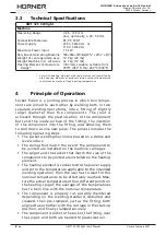
3.3 

Technische Daten

HWT 125  SW light

Maschine

Arbeitsbereich

Geeignete Materialien
Stromversorgung

Maximale Leistungsaufnahme
Platzbedarf Maschine in Betrieb
Gewicht Klemm-/Einspanneinheit
Gesamtgew. Maschine m. allem Zubeh.
Temperaturbereich des Heizelements*

)

ø 63 - 125 mm 
zzgl. optional ø 20 - 50 mm
PE, PP, PVDF
230 V, 50/60 Hz   

oder

110 V, 50/60 Hz
1,5 kW
700 × 560 × 470 mm
10,9 kg
32,7 kg
stufenlos einstellbar von 
200°C bis 260°C

*)  nur bei Heizelement mit nutzergeregelter Temperatur; Heizelement 

der Ausführung ohne Temperaturregelung ab Werk auf Konstanttem-
peratur eingestellt

4 Funktionsprinzip

Beim Muffenschweißen handelt es sich um ein Verfahren, bei 
dem zwei Werkstücke miteinander verbunden werden, indem 
beide in zwei Schweißungen in eine Muffe mit etwas größerem 
Durchmesser als die Werkstücke hineingeschweißt werden. Die 

Verbindung wird durch Plastifizierung des Werkstückendes und 

der Schweißmuffeninnenseite, Hineinschieben des Werkstücks 
in die Muffe und Abkühlen als feste Verbindung erzielt. Zu 
dem Verfahren gehören folgende Ablaufschritte:

•  Die Muffenschweißmaschine wird auf auf eine sichere und 

plane Standfläche gestellt.

•  Die Spannwerkzeuge, die zum Durchmesser der zu verbin

-

denden Werkstücke passen, werden auf der Grundmaschi-
ne montiert.

•  Die Heizmuffe und der Heizdorn, die zum Durchmesser 

der zu verbindenden Werkstücke passen, werden auf das 
Heizelement aufgesetzt.

•  Das  Heizelement  wird  an  die  Stromversorgung  ange

-

schlossen und die Temperatur, die für die beabsichtigte 
Verschweißung gilt, eingestellt. Es ist dann zu warten, bis 
diese Solltemperatur erreicht ist. Die Isttemperatur ist am 
Heizdorn an vier Punkten zu messen und der Durchschnitt 
aller vier Messungen muss beim Sollwert liegen.

•  Das Werkstück wird sauber zugeschnitten, je nach Schweiß

-

norm ggf. angefast, entgratet und gereinigt, sodann lose 
eingespannt, ebenso die Schweißmuffe, beide in Nullstel-
lung der Schlitten aneinander ausgerichtet und schließlich 
fest eingespannt.

•  Das Werkstück wird in die Heizmuffe, die Schweißmuffe 

über den Heizdorn geschoben und beide bis zur Plastifi

-

zierung erhitzt.

Summary of Contents for HWT 125 SW light

Page 1: ...r Ohmener Str 26 35325 M cke Atzenhain 49 0 6401 91 27 0 49 0 6401 91 27 39 info huerner de http www huerner de H RNER SCHWEISSTECHNIK GmbH Version Februar 2021 Bedienungsanleitung User s Manual Manue...

Page 2: ...ected in both translations herein La version allemande ci apr s repr sente le texte original du manuel rendu par les deux traductions ci joint La versi n alemana adjunta est el texto original de las i...

Page 3: ...2 Arbeitsumfeld 6 2 3 Bestimmungsgem er Gebrauch 6 3 Maschinenbeschreibung 7 3 1 Gesamtansicht 7 3 2 Transport Lagerung Versand 7 3 3 Technische Daten 8 4 Funktionsprinzip 8 5 Bedienung 9 5 1 Vorberei...

Page 4: ...Version Februar 2021 4 DE Bedienungsanleitung HWT 125 SW light H R N E R S c h w e i s s t e c h n i k G m b H Nieder Ohmener Str 26 35325 M cke Deutschland...

Page 5: ...s Produkt und andere Sachwerte des Betreibers die effiziente Arbeit des Produkts Alle Personen die mit der Inbetriebnahme Bedienung War tung und Instandhaltung des Produkts zu tun haben m ssen entspre...

Page 6: ...Schwei maschine wurde f r die Verbindung durch Muf fenschwei ung von Rohren und oder Formteilen aus thermo plastischen Kunststoffen entwickelt und gefertigt Sie ist nur f r in ihrem technischen Datenb...

Page 7: ...elden Sie dem Spediteur etwaige M ngel oder feh lende Teile Sp tere Beschwerden berechtigen unter Umst nden nicht mehr zur M ngelbeseitigung Wichtig Nach dem Schwei en darf die Maschine insbesondere i...

Page 8: ...erung des Werkst ckendes und der Schwei muffeninnenseite Hineinschieben des Werkst cks in die Muffe und Abk hlen als feste Verbindung erzielt Zu dem Verfahren geh ren folgende Ablaufschritte Die Muffe...

Page 9: ...eizmuffe dorn ver wendet ist kein ordnungsgem es Schwei ergebnis gew hrleistet und der Hersteller ist von der Haftung und Gew hrleistung f r das Produkt entbunden Die n tigen Spannelemente bestehen au...

Page 10: ...g die Maschine entsprechend um In diesem Fall ist in den folgen den beiden Abschnitten mit das Stellrad f r beide Schlitten jeweils der Akkuschrauber der ber den zugeh rigen Adapter die Schlitten bewe...

Page 11: ...hr und Muffe heraus und fahren Sie beide Werkst cke in den Spannelementen auf einander zu um abschlie end den Versatz zu pr fen und falls n tig zu korrigieren 6 Fahren Sie die Schlitten mithilfe des S...

Page 12: ...n ist und fahren Sie dann die Maschine auseinander und so die Werk st cke vom Heizelement weg Entnehmen Sie das Heizelement und schieben Sie die Werkst cke mit Hilfe des Stellrads inein ander bis die...

Page 13: ...n muss vollst ndig sauber und durch nichts eingeschr nkt oder gehindert sein 7 Wartung und Pflege Reinigen Sie die Maschine nach jedem Auftrag sorgf ltig insbesondere wenn f r diesen Auftrag oft oder...

Page 14: ...e WEEE Richtlinie nehmen wir von uns hergestellte bzw in Verkehr gebrachte Altger te zur ck Um das exakte Verfahren abzustimmen sprechen Sie uns unter der Anschrift unten an Wir erkl ren weiterhin das...

Page 15: ...Heizmuffe 25 mm DVS Typ B 200 230 150 Heizdorn und Heizmuffe 32 mm DVS Typ B 200 230 141 Heizdorn und Heizmuffe 40 mm DVS Typ B 200 230 142 Heizdorn und Heizmuffe 50 mm DVS Typ B 200 230 143 Heizdorn...

Page 16: ......

Page 17: ...rk Environment 6 2 3 Intended Use 6 3 Machine Description 7 3 1 Component Overview 7 3 2 Transport Storage Shipment 7 3 3 Technical Specifications 8 4 Principle of Operation 8 5 Operation 9 5 1 Prepar...

Page 18: ...Version February 2021 4 EN HWT 125 SW light User s Manual H R N E R S c h w e i s s t e c h n i k G m b H Nieder Ohmener Str 26 35325 M cke Germany...

Page 19: ...xpose the following to hazards the operator s health the product and other assets of the operating entity the efficient work of the product All persons involved in the installation operation main tena...

Page 20: ...plastic material by the socket fusion process It shall be used only for the materials quoted in its technical specifi cations and for components with one of the diameters for which heating spigots and...

Page 21: ...fects or missing part Complaints at a later time may no longer be eligible for remedy Important When the user is done welding the machine in particular its heating element must not be stored wrapped b...

Page 22: ...hrough the plasticization of the component butt and the inside surface of the fitting the insertion of the component into the fitting and allowing them to cool down as one new piece The process includ...

Page 23: ...use of any other heating spigot or socket puts the welding operation at risk of yield ing a poor outcome and will in all cases dispense the manufacturer from assuming any liability or responsibility...

Page 24: ...elding to move the carriages another prepara tion is to reconfigure the machine like this If so interpret the expression using the handwheel moving both carriages in the following two sec tions as mea...

Page 25: ...operator is Then turn the handwheel for the clamps on the pipe side on to where the pipe is clamped fast between their jaws 5 Remove the heating element from in between the pipe and the fitting if it...

Page 26: ...3 be sure to set the tool to its lowest speed and lowest operating force If the tool turns too fast or exercises too much force you run the risk of a hand injury Wait for the heating time see Sect 5...

Page 27: ...Wall Thickness mm Heating Stage sec Change over Stage max sec Cooling Stage Clamped s Total min 20 1 9 6 4 6 2 25 1 9 8 4 6 2 32 2 4 10 4 12 4 40 2 4 12 4 12 4 50 3 18 4 12 4 63 3 20 6 18 6 75 3 22 6...

Page 28: ...ng still warm sockets and spigots in any way always wear heat resistant protective gloves Important Using water in any way e g for cooling or clean ing with the machine or the sockets and spigots is s...

Page 29: ...75 mm DVS type A 200 230 034 Heating Socket Spigot 90 mm DVS type A 200 230 035 Heating Socket Spigot 110 mm DVS type A 200 230 036 Heating Socket Spigot 125 mm DVS type A 200 230 037 Product version...

Page 30: ......

Page 31: ...6 2 3 Usage pr vu 6 3 Descriptif de la machine 7 3 1 Vue d ensemble des l ments 7 3 2 Transport stockage exp dition 7 3 3 Fiche technique 8 4 Principe de fonctionnement 8 5 Fonctionnement 9 5 1 Pr par...

Page 32: ...Version F vrier 2021 4 FR Manuel utilisateur HWT 125 SW light H R N E R S c h w e i s s t e c h n i k G m b H Nieder Ohmener Str 26 35325 M cke Allemagne...

Page 33: ...les de nuire la sant de l usager d endommager le produit et d autres mat riels de l exploi tant de diminuer l efficacit du produit Toute personne responsable de la mise en service de la mani pulation...

Page 34: ...e pour l assemblage par le proc d dit par embo tement des tubes et ou pi ces de tuyauterie faits de mati res thermoplastiques Elle ne sera utilis e que pour les mati res cit es sur sa fiche technique...

Page 35: ...ant d faut l attention du transporteur Des plaintes tardives risquent de ne plus ouvrir droit une compensation Important la fin des soudages il est d fendu de stocker embal ler la machine son l ment c...

Page 36: ...de la pi ce et de la surface int rieure du raccord l embo tement de la pi ce dans le raccord et le refroidissement du nouvel assemblage Le proc d passe par les tapes suivantes La soudeuse est mise en...

Page 37: ...la machine L utilisation d un bout m le ou femelle chauffant autre que ceux l ne saurait assurer le r sultat escompt du soudage et rend caduques la responsabilit et la garantie du fabricant dont le p...

Page 38: ...tir la machine de la sorte Si tel est le cas au lieu de l expression l aide du volant commandant les deux chariots aux deux sections suivantes lire l aide de la visseuse sans fil qui fait bouger les c...

Page 39: ...mement 5 S il y a t positionn afin d aligner les pi ces l une sur l autre enlever l l ment chauffant entre le tube et le raccord et rapprocher les deux l un de l autre dans les mors de serrage pour po...

Page 40: ...Si elle tournait trop vite ou avec trop de force il y aurait un risque de blessure des mains Attendre que le temps de chauffe se soit coul voir la sec tion 5 4 puis carter les pi ces assembler de l l...

Page 41: ...t Immobilis s Total min 20 1 9 6 4 6 2 25 1 9 8 4 6 2 32 2 4 10 4 12 4 40 2 4 12 4 12 4 50 3 18 4 12 4 63 3 20 6 18 6 75 3 22 6 18 6 90 3 25 6 18 6 110 3 30 6 24 8 125 6 D pannage Probl me Solution Le...

Page 42: ...tion de ceux ci lorsqu ils sont encore chauds porter imp rativement des gants de protection qui r sistent la chaleur Important L utilisation de l eau sur la machine ou les bouts m les et femelles quel...

Page 43: ...auffants 75 mm DVS type A 200 230 034 Bouts m f chauffants 90 mm DVS type A 200 230 035 Bouts m f chauffants 110 mm DVS type A 200 230 036 Bouts m f chauffants 125 mm DVS type A 200 230 037 Mod le DVS...

Page 44: ......

Page 45: ...pci n de la m quina 7 3 1 Vista sin ptica de los elementos 7 3 2 Transporte almacenaje expedici n 7 3 3 Especificaciones t cnicas 8 4 Principio funcionamiento 8 5 Funcionamiento 9 5 1 Preparaci n de l...

Page 46: ...H R N E R S c h w e i s s t e c h n i k G m b H Nieder Ohmener Str 26 35325 M cke Alemania Versi n Febrero de 2021 4 ES Manual de instrucciones HWT 125 SW light...

Page 47: ...o siguiente est expuesto a peligro y fallos La salud del operario Otra maquinaria involucrado en el proceso Funcionamiento correcto del producto Todos los personales involucrados en los procesos de la...

Page 48: ...para el en samblaje de tuber as y o accesorios de pl stico por el proceso llamado a socket No deber nunca ser usada para materiales no indicados por sus especificaciones t cnicas as como solo para pie...

Page 49: ...ieza haciendo falta Reclamaciones con retraso podr an cancelar el derecho de restituci n Importante Las soldaduras finalizadas es prohibido almacenar encajonar la m quina su elemento calefactor en par...

Page 50: ...ponente y de la superficie interna del accesorio del encaje del componente dentro del accesorio y del enfriamiento de esta rea de ensamblaje El proceso tiene los siguientes pasos La soldadora se coloc...

Page 51: ...m quina El uso de un molde macho o hembra distinto de aquellos no puede garantizar el xito esperado de la soldadura y tiene como consecuencia la p rdida de la garant a y de la responsabilidad del prod...

Page 52: ...reparativo es de modificar la m quina para esta configuraci n Si est as cada vez que los siguientes dos puntos indican usando el volante que mueve los carros esta expresi n se debe interpretar como us...

Page 53: ...a tuber a inm vil 5 Si fue introducido para ajustar la posici n de los compo nentes retire el elemento calefactor entre la tuber a y el accesorio y aproxime ambos apretados por las abrazade ras uno a...

Page 54: ...irara demasiado r pidamente o con demasiado fuerza se correr a el riesgo de lesiones de la mano Espere que pase integralmente el tiempo de calentamiento v punto 5 4 a continuaci n separe los component...

Page 55: ...mm Fase de ca lentamiento sec Fase de pues ta en contac to m x sec Fase de enfriamiento Apretado s Total min 20 1 9 6 4 6 2 25 1 9 8 4 6 2 32 2 4 10 4 12 4 40 2 4 12 4 12 4 50 3 18 4 12 4 63 3 20 6 1...

Page 56: ...los residuos en los moldes machos y hembras y todos otros manejos de los mismos cuando siguen calientes lleve siempre guantes de seguridad contra el calor Importante El uso de agua acerca de la m quin...

Page 57: ...de calef D 75 mm DVS tipo A 200 230 034 Moldes m h de calef D 90 mm DVS tipo A 200 230 035 Moldes m h de calef D 110 mm DVS tipo A 200 230 036 Moldes m h de calef D 125 mm DVS tipo A 200 230 037 Model...

Page 58: ......

Page 59: ...3 Descrizione della macchina 7 3 1 Riassunto degli elementi 7 3 2 Trasporto conservazione spedizione 7 3 3 Dati tecnici 8 4 Principio di funzionamento 8 5 Funzionamento 9 5 1 Preparazione della salda...

Page 60: ...H R N E R S c h w e i s s t e c h n i k G m b H Nieder Ohmener Str 26 35325 M cke Germania Versione Febbraio 2021 4 IT Manuale d uso HWT 125 SW light...

Page 61: ...dell operatore il prodotto e altro hardware dell operatore l efficiente funzionamento del prodotto Tutti i soggetti coinvolti nell installazione funzionamento cura e manutenzione del prodotto devono...

Page 62: ...ccordi di materiale plastico utilizzando il metodo chiamato saldatura a bicchiere Non dovr mai venir utilizzato per materiali non menzionati nei suoi dati tecnici e inoltre solamente per pezzi con un...

Page 63: ...to o elementi assenti Se il reclamo fosse tardivo potrebbe essere escluso il diritto di restituzione Importante Finiti gli interventi di saldatura vietato stoccare incassare la macchina in particolare...

Page 64: ...nterna del raccordo l inserzione del pezzo nel raccordo e il raffreddamento di questa zona di giunzione Il procedimento ha le tappe qui sotto La saldatrice viene piazzata a un posto piano e solido Le...

Page 65: ...crizione tecnica L utilizzo di una bussola femmina o maschio diversa di quelle non pu garantire l esito desiderato della saldatura e annuller la responsabilit e la garanzia per il prodotto che il suo...

Page 66: ...fica della macchina In questo caso nelle due sezioni qui sotto ogni volta che si scrive utilizzando il volantino per il movimento dei carrelli quest espressione si deve intendere come utilizzando l av...

Page 67: ...ta immessa tra i pezzi per allinearli togliere la piastra riscaldante tra il tubo e il raccordo e avvicinare l uno all altro tutti i due trovandosi nelle ganasce per controllare un ultima volta e all...

Page 68: ...troppo forza ci sarebbe il rischio di ferite della mano Aspettare che il tempo di riscaldamento sia integralmente passato v sezione 5 4 poi staccare i pezzi dalle bussole riscal danti movimentando i...

Page 69: ...ete del tubo mm Fase di riscalda mento sec Fase di cambio max sec Fase di raffreddamento Fissato s Totale min 20 1 9 6 4 6 2 25 1 9 8 4 6 2 32 2 4 10 4 12 4 40 2 4 12 4 12 4 50 3 18 4 12 4 63 3 20 6 1...

Page 70: ...femmine e maschi e tutte le altre manovre con le stesse quando continua no di essere calde mettere obbligatoriamente guanti di protezione resistenti al calore Importante L utilizzo di acqua attorno a...

Page 71: ...A 200 230 034 Bussole riscaldanti m f dia 90 mm DVS tipo A 200 230 035 Bussole riscaldanti m f dia 110 mm DVS tipo A200 230 036 Bussole riscaldanti m f dia 125 mm DVS tipo A200 230 037 Modello DVS tip...

Page 72: ...razione conforme alle seguenti norme i documenti di stan dardizzazione CE Konformit t Conformit CE Conformit CE Directive 2014 30 EU Directive 2012 19 EU Directive 2014 35 EU Directive 2006 42 EC Ande...

Page 73: ...conforme a las siguientes normativas o documentos de nor malizaci n CE Conformity Conformidad CE CE Directive 2014 30 EU Directive 2012 19 EU Directive 2014 35 EU Directive 2006 42 EC Other Standards...

Reviews: