


FORM NO. 41068-01 8/95
- 2 -
©1995 HUNTER FAN CO.
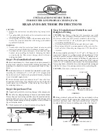
Step 4: Installation of Ceiling Plate
A.
Install the (4) rubber bushings into the top of the ceiling plate
by inserting small side of the bushing into the four holes in the
ceiling plate. See Figures 4 and 4A.
FIGURE 4
FIGURE 4A
FIGURE 4B
BUSHING
CEILING PLATE
B.
Thread the lead wires through the opening in the top of the
ceiling plate and through the opening in the side of the hanger
bracket. See Figure 4B.
Using the two center slots, install the ceiling plate to the 2 x 4
brace which supports the outlet box. Use (2) #10 woodscrews 3"
long and (2) flatwashers for mounting. Drill (2) pilot holes for the
mounting screws 9/64" diameter. See Figure 4B.
NOTE: When attaching ceiling plate to the outlet box support,
make certain bushings remain in place.
NOTE: Tighten the ceiling plate mounting screws only enough to
provide slight compression of the bushings. Do not over-tighten.
BUSHING
OUTLET BOX
2 x 4 BRACE
HANGER BRACKET
CEILING
PLATE
FLAT WASHER
MOUNTING
SCREWS
FIGURE 5A
FIGURE 5
Step 5: Hanging of Motor
CAUTION: Do not lift motor by wires.
A.
Lift the motor and insert the plastic hanger into the opening in
the front of the hanger bracket. See Figure 5. Make sure none of
the wires are trapped between the plastic hanger and the inside of
the hanger bracket.
B.
Rotate the motor and plastic hanger assembly until the lower
half of the plastic hanger fits into the square opening in the bottom
of the metal bracket. Check the assembly by trying to rotate the
motor and plastic hanger assembly. When properly installed the
upper part of the plastic hanger will sit flat inside the hanger and
the assembly will not rotate. See Figure 5A.
PLASTIC
HANGER
MOTOR
HANGER
BRACKET
HANGER BRACKET
FIT LOWER HALF
OF PLASTIC
HANGER INTO
SQUARE HOLE IN
BOTTOM OF
HANGER BRACKET
CAUTION: Make sure plastic hanger can not rotate in metal
bracket. Failure to check this could result in the motor falling.
NOTE: The green ground wire attached to the plastic hanger should
face the opening in the front of the metal hanger bracket.


