background image

Network


Dome


Camera

Quick


Operation


Guide


4

Safety


Instru

These


instruction

product


correctl

The


precaution


m

Cautions:

Injury

cautions


are


negl

Warnings


In


the


use


of


the


product,


you


must


be


in


strict


compliance


with


the


electrical


safety


regulations


of


the


nation


and


region.


Please


refer


to


technical


specifications


for


detailed


information.


Input


voltage


should


meet


both


the


SELV


(Safety


Extra


Low


Voltage)


and


the


Limited


Power


Source


with


24


VAC


or


12


VDC


according


to


the


IEC60950

1


standard.


Please


refer


to


technical


specifications


for


detailed


information.


ction


s


are


intended


to


ensure


that


user


can


use


the


y


to


avoid


danger


or


property


loss.


easure


is


divided


into


“Warnings”


and


“Cautions”


Warnings:


Serious


injury


or


death


may


occur


if


any


of


the


warnings


are


neglected.


or


equipment


damage


may


occur


if


any


of


the


ected.


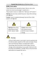
Warnings


Follow


these


safeguards


to


prevent


serious


injury


or


death.

Cautions


Follow


these


precautions


to


prevent


potential


injury


or


material


damage.


Summary of Contents for HNC301?VD

Page 1: ...1 Camera ork Dome Camera Netw Quick Operation Guide...

Page 2: ...We will readily improve or update the products or procedures described in the manual DISCLAIMER STATEMENT Underwriters Laboratories Inc UL has not tested the performance or reliability of the security...

Page 3: ...oHS Directive 2011 65 EU FCC compliance This eq comply with the limits for a digital device purs igned to p rference vironment Th requency ener instruction m interference to radio communications Opera...

Page 4: ...duct to your local supplier upon the purchase of equivalent new equipment or dispose of it at designated collection points For more informa see www recyclethis info 2006 66 EC battery directive This p...

Page 5: ...ty Extra Low Voltage and the Limited Power Source with 24 VAC or 12 VDC according to the IEC60950 1 standard Please refer to technical specifications for detailed information ction s are intended to e...

Page 6: ...e over heating or a fire hazard Please make sure that the plug is firmly connected socket When the product is mounted on wall or ceiling the device shall be firmly fixed If smoke o at once and unplug...

Page 7: ...cumulation good operating environment Keep the camera away from liquid while in use While in delivery the gul pl tor of the according to their average enduring time The average time varies because of...

Page 8: ...26 31 Table of Contents 1 Appearance Description 2 Installation 2 1 Disassembling 2 2 Mounting 2 2 1 Ceiling Moun 2 2 2 Ceiling Mounting with Gang Box 2 2 3 Wall Mounting 2 3 Image and Focus Adjustin...

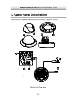
Page 9: ...Network Dome Camera Quick Operation Guide 1 Appearance Description The overview of the network dome camera is shown below 8 Figure 1 1 Overview 4 2 3 1 9 10 5 6 7 11 8...

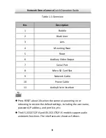
Page 10: ...Port 8 Micro SD Card Slot 9 Network Cable 10 Power Cable 11 Audio Alarm Interface z Press RESET about 10s when the camera is powering on or rebooting to restore the default settings including the use...

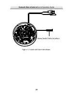
Page 11: ...Network Dome Camera Quick Operation Guide Alarm Audio Cable Interface 10 Figure 1 2 Audio and Alarm Interfaces...

Page 12: ...product does not function properly please contact your dealer or the nearest service center Do not disassemble the z Make sure that the wall is strong enough to withstand three times the weight of th...

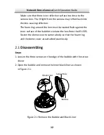
Page 13: ...ubble and Black Liner Make sure that ther camera lens The IR the lens caus The foam ring around the lens must be seated flush against the inner surface of the bubble to isolate the lens from the IR LE...

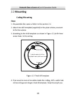
Page 14: ...side the ceiling ble hole in the ceiling according to the drill template Skip if you Steps 1 Disassemble the camera Refer to the section 2 1 2 Attach the drill template supplied to the place wh to fix...

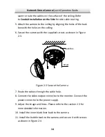
Page 15: ...the cable hole 8 Connect the video output connector to the monitor Connect the power connector to the power supply 9 Ad tion 2 3 for more detailed information 11 Install the bubble back to the camera...

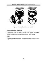
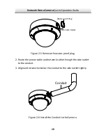
Page 16: ...ck Liner and Bubble Conduit Installation on the Side If you want to route the cables from side of the camera you need to follow the steps below to install a conduit for cable routing Steps 1 Ro remove...

Page 17: ...de Cable Outlet 16 Figure 2 5 Remove the water proof plug side outlet to the conduit onduit to the side outlet tightly Figure 2 6 Install the Conduit to the Camera 2 Route the power cable and network...

Page 18: ...ide outlet directly downward for water proof Figure 2 7 Side Outlet Direction 2 2 2 Ceiling Mounting with Gang Box Steps 1 Disassemble the camera Refer to the section 2 1 2 Install the gang box in the...

Page 19: ...center of the mounting base 5 Align 6 Tighten the screws to secure the camera with the mounting base monitor Connect the r connector to the power supply ion 2 3 for the camera with the mounting base...

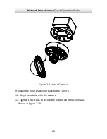
Page 20: ...Quick Operation Guide Figure 2 9 Secure Camera 9 Install the inner black liner back to the camera 10 Align the bubble with the camera 11 Tighten the screws to secure the bubble with the camera as show...

Page 21: ...to purchase a wall mount Steps 1 Disassemble the camera Refer to the section 2 1 shown in Figure les of the mounting adapter 4 Secure the mounting base to the mounting adapter with four screws 2 Inst...

Page 22: ...secure the camera with the mounting 2 3 for Figure 2 11 Install the Mounting Ba 5 Route the cables throu 6 Align the camera with the mounting base 7 Tight base 8 Connect the video output connector to...

Page 23: ...me Camera Quick Operation Guide 22 ra the inner black liner back to the camera e with the camera Figure 2 12 Secure Came 10 Install 11 Align the bubble with the camera 12 Tighten the screws to secure...

Page 24: ...and Focus Adjusting Steps monitor the camera 3 Rotate the tilting axes to adjust the tilting position of the camera 4 Rotate the lens table to adjust the azimuth angle of the image 1 3 axis adjustmen...

Page 25: ...m lever and move the lever between T Tele obtain the appropriate angle of view to obtain the optimum focus 2 Zoom and focus adjustment 1 View the camera image using the monito 2 Lo and W Wide to 3 Tig...

Page 26: ...Network Dome Camera Quick Operation Guide Zoom Focus Lever 25 Figure 2 15 Lens Adjustment...

Page 27: ...and change the IP of network camera The following figure shows the cable connection of netw k camera and PC Figure 3 1 Wiring over LAN Set the IP address of the camera for accessing via LAN Steps 1 T...

Page 28: ...s the total number and information of the searched devices in the Online Devices interface Device information including the device type IP address port number gateway etc will be displayed to the user...

Page 29: ...be searched and displayed in the list in 15 seconds after it goes online it will be removed from the list in 45 seconds after it goes offline Search online devices manually You can also click to refr...

Page 30: ...ce to be modified in the device list as shown in Figure 3 3 The network parameters of the device will be rs panel on the Edit the modifiable network parameters e g IP address and port number Enter the...

Page 31: ...alue of the IP address is 192 0 0 64 The default user name is admin and password is 12345 For accessing the network camera from different subnets please set the gateway for the network camera after yo...

Page 32: ...AM 1G or higher Display 1024 768 resolution or higher Web Browser Internet Explorer 6 0 and above version Apple Safari 5 02 and above version Mozilla Firefox 3 5 and above version and Google Chrome8 a...

Page 33: ...Interface all the plug in before viewing the live video and managing the installation prompts to install the finish the installation of Figure 4 1 Login 5 Inst the camera Please follow plug in You may...

Page 34: ...Network Dome Camera Quick Operation Guide Figure 4 2 Download Plug in 33 Figure 4 3 Install Plug in 1...

Page 35: ...Guide 34 Figure 4 4 Install Plug in 2 6 Re of the plug in and repeat the steps 2 4 to login For detailed instructions of further configuration please refer to the user manual of network camera open th...

Page 36: ...Network Dome Camera 0 a Quick Operation Guide 0...

Reviews: