background image

 
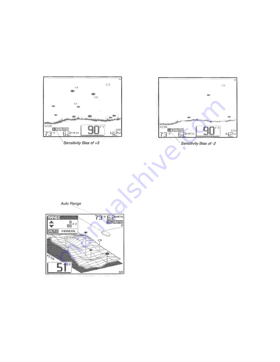
  A setting of –2 sets the sensitivity two steps below what the unit would normally select, so only 
the largest targets of other returns are displayed. 
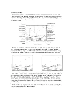
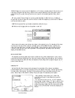
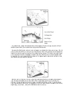
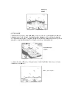
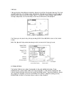
  Another use of the Sensitivity menu is to select the bottom representation. In the 2D view the 
Wide 3D View normally displays a variable Structure ID bottom, which can allow experienced 
users to determine the texture or relative hardness of the bottom. For simplicity, you can select a 
black bottom using the ENTER button. This blackens in the display below the bottom for easiest 
recognition of the bottom location, even from a great distance. 


RANGE 
 
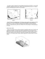
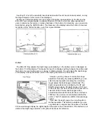
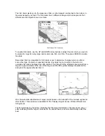
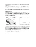
  The Wide 3D View adjusts the depth range automatically, so the bottom return is displayed at 
the bottom 1/3 of the display. This leaves the top 2/3 to display anything between the surface and 
the bottom. As your boat moves over deeper or shallower water, the unit adjusts the depth range 
of the display to keep the bottom return in the same general area on the screen. 
 

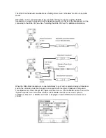
  However, you may choose to control this range 
adjustment manually. By pressing ENTER, you can 
select manual operation, meaning the unit will no 
longer adjust the depth range automatically. The 
depth range selected is controlled by the UP and 
DOWN arrow buttons. 3D depth ranges of 0-15 feet, 
30 feet, 60 feet, 120 feet, 180 feet, & 240 feet can be 
selected. In the 2D view depth ranges will be 
extended and include 360 feet, 480 feet, 600 feet, & 
1000 feet. An on-screen icon indicates whether the 
unit is in “AUTO” (automatic) or MNL (manual) range 
control. 
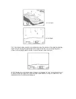
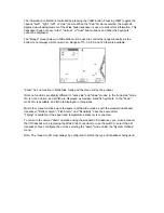
  If you alter the depth range, the unit will switch to 
manual operation. This feature is valuable if you are 
only interested in targets near the surface. The Wide 

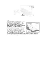
3D View will always display the digital depth of the water in the manual mode. If the bottom is not 
visible in the depth range selected, a 3D grid will be shown for reference. 
 

Summary of Contents for Wide 3D View

Page 1: ......

Page 2: ...h our number listed in the Customer Support section INSTALLATION OVERVIEW Your Humminbird fishfinder consists of two primary components to install the control head and the transducer The control head contains the sonar transmit and receive circuitry as well as the user controls and display It should be installed in a location that provides access to the controls and visibility while in use The con...

Page 3: ... should the boat strike debris in the water or when trailering As an alternative to transom mounting it is possible on many fiberglass hulled boats to glue the transducer on the inside of the boat hull Since fiberglass has similar sonar characteristics as water the sonar signal can pass through the boat hull with minimal loss The hull of the boat must be single layer construction not double hulled...
Page 4: ... other surface Trolling Motor Mounting The standard transducer can also be adapted to mount on most trolling motors using a different accessory kit This accessory includes a bracket and hose clamp that allows mounting the transducer to the body of most trolling motors Thru Hull Mounting Thru hull transducers install through a hole drilled in the hull of the boat Larger boats or boats with inboard ...

Page 5: ...mminbird fishfinder The installation guide included on the next few pages provides detailed step by step instructions for installation of the control head and transducer For transom mount transducer installations you will need the mounting template included with your manual In addition to the parts included you need the following for installation and operation A powered hand drill and various dril...

Page 6: ...f the propeller s This turbulent water is normally confined to areas immediately aft of ribs strakes or rows of rivets on the bottom of the boat and in the immediate area of the propeller s Figure 1 On outboard or inboard outboard boats it is best to stay at least 15 40cm to the side of the propeller s If possible viewing the transom of the boat while the boat is moving will provide the best means...

Page 7: ...ng a 5 32 4mm bit drill the two holes to a depth of approximately 1 3cm On fiberglass hulls it is best to start with a smaller bit and use progressively larger drill bits to reduce the chance of chipping or flaking the outer coating Step Three Assemble the Transducer 1 Attach the Pivot to the transducer body as shown in Figure 5 using the 8 3 8 9mm long allen headed pivot screw the headed pin the ...

Page 8: ...Further adjustment may be necessary to refine the instillation after high speed testing 1 First adjust the pivot angle of the transducer body so its length is parallel with the length of hull of the boat Then pivot the transducer down so the rear is about 1 4 inch 6mm lower than the front Figure 9 2 Fully tighten the two pivot screws using the Allen wrenches It may be necessary to retighten the pi...

Page 9: ...mounting bracket Drill this hole and install the screw after final testing and adjustments have been completed ...

Page 10: ...terference If the cable is too short extension cables are available to extend the transducer cable up to a total of 50 15 m Call Humminbird Customer Support for more information Follow these steps to route the cable through the transom 1 Drill a 5 8 16mm hole above the water line Route the cable through the hole 2 Fill the hole with silicone sealant 3 Place the escutcheon plate over the hole and a...

Page 11: ...ounting Location Begin the transducer installation by determining where inside the hull to install the transducer Consider the following to find the best location Observe the outside of the boat hull to find the areas that are mostly free from turbulent water Avoid ribs strakes and other protrusions as these create turbulence Figure 14 As a general rule the faster the boat can travel the further a...

Page 12: ...The transducer cannot transmit through air The water purges any air from between the transducer and the hull and fills any voids in the coarse fiberglass surface ...

Page 13: ...y dry the mounting surface If the surface is excessively rough it may be necessary to sand the area to provide a smooth mounting surface Ensure the mounting area is clear and dry 3 Mix an ample quantity of two part slow cure epoxy slowly and thoroughly Avoid trapping air bubbles 4 Coat the face of the transducer and the inside of the hull Figure 16 5 Press the transducer into place with a slight t...

Page 14: ... supplied hole cover The mounting surface should be adequately supported to protect the fishfinder from excessive wave shock and vibration and provide visibility while in operation The mounting area should allow sufficient room for the unit to pivot and swivel freely and for easy removal and installation Figures 18 19 Step Two Connect the Power Cable to the Boat A 6 2m long power cable is included...

Page 15: ...fuse in the connection If you must wire the control head directly to a battery be sure to install an inline fuse holder ...

Page 16: ...e mounting surface mark and drill a 1 25mm hole centered between the four mounting holes Figure 22 Note if the cables must pass through the mounting surface at a different location drill the 1 25mm hole at that location and pass the cables through from underneath Also you must break out the tabs on the rear of the mounting base using needle nose pliers Figures 24 25 2 Insert all cables through the...

Page 17: ...Optional If the cables pass outside the mounting bracket install the hole cover over the hole and fasten in place using the two 8 x 7 8 22mm wood screws Figure 24 ...

Page 18: ...ull the excess cable from beneath the mounting surface so the connector holder aligns with the mounting holes on the front of the mounting bracket Figure 27 3 Snap the support plate to the rear of the connector holder Figure 28 4 Insert the connector holder into place and use the two 6 32 x 9mm screws to fasten it to the mounting bracket Figure 28 5 Install the control head by sliding it onto the ...

Page 19: ...ormal operation unless you choose another option If you do not press any button before the timer reaches 0 the normal operation screen is displayed If the boat is in water sonar data appears If the bottom is visible on screen with a digital depth readout the unit is working properly Ensure the boat is in water greater than 2 but less than the depth capability of the unit and the transducer is full...

Page 20: ...d In some situations the selected point of view may prevent the display of some information due to the slope of the terrain If you are traveling in a direction which will present this situation for an extended period of time an option is available to reverse the view point to the opposite side of your boat which enables you to see information that would otherwise be masked by the terrain The norma...

Page 21: ...est for determining bottom hardness and texture and locating structure or bottom detail The combo view combines both 3D and 2D views to provide the best of both views USING THE 3D VIEW At power up the Wide 3D View locates the bottom and adjusts the depth range to a setting most appropriate for that depth The bottom will usually be displayed about 2 3 of the way down the display Each of the six son...

Page 22: ...w The 200 kHz transducer will provide reliable target and bottom tracking to a depth of 1000 feet If a target is detected between the surface and the bottom and it meets the fish identification criteria it is displayed as a fish symbol Sonar returns that do not meet this criteria are displayed as raw information Depending on the strength of the signal reflected from the target and other factors on...

Page 23: ...l not be seen in the 2D view Using a narrower beam provides much more detailed information as to the composition of the bottom If the bottom is hard and smooth the bottom depiction will be narrow and dense If the bottom is mud or soft sand the bottom depiction will be thick and less dense This indicates that much of the solar signal is absorbed by the soft bottom If the bottom is rugged and varyin...

Page 24: ... normal operation Also if the unit is powered off press and hold POWER until you hear a continuous chirp to enable simulator operation as discussed in Simulator Operation Pressing POWER when the unit is in normal or simulator operation will power the unit off STOP freezes the display to allow closer study Pressing STOP again will resume normal operation Also if a menu is on screen STOP will retain...

Page 25: ... MENU repeatedly will sequentially display all available menus MENU FUNCTIONS The following section explains each menu in detail and how these adjustments can be used to extract the maximum information from the sonar returns With several exceptions once a setting has been changed the Wide 3D View will remember that setting until it is again changed even if power is disconnected SENSITIVITY As the ...

Page 26: ...es over deeper or shallower water the unit adjusts the depth range of the display to keep the bottom return in the same general area on the screen However you may choose to control this range adjustment manually By pressing ENTER you can select manual operation meaning the unit will no longer adjust the depth range automatically The depth range selected is controlled by the UP and DOWN arrow butto...

Page 27: ...determined by the depth range in use when Zoom is enabled In shallow water when the 15 foot or 30 foot depth range is used the zoom range will be 7 feet If the 60 foot or 120 foot depth range is in use the zoom range will be 15 feet And if the 180 foot or 240 foot depth range is in use the zoom range will be 30 feet For depths greater than 240 feet the display will only update a 2D view If the dep...

Page 28: ...2D view but displays a zoomed 3D view The Zoom menu will not appear when an adjustment is made unless MENU is pressed The digital depth readout will continue to track the bottom even when Zoom is enabled Bottom Lock is a function of zoom except the depth adjustment is controlled automatically to view the area immediately above the bottom This is especially useful if you are looking for structure o...

Page 29: ...enable the alarm simply adjust the alarm depth using the UP and DOWN arrow buttons and press ENTER When the depth of the water beneath your boat is equal to or less than the selected alarm depth a continuous alarm will sound To disable the alarm either move to deeper water or select the Bottom Alarm menu and press ENTER to turn the alarm off ...

Page 30: ...ome other type of object or suspended debris Any object not connected to the bottom is normally a fish and is portrayed as a fish symbol The strength of the reflected sonar signal from a target is a good indicator of the size of the target and the fish symbol displayed represents the strength of the signal reflected from it ID is the automatic identification of target returns based on the strength...

Page 31: ...get When there are numerous targets on screen not every target depth is shown to avoid excessive clutter on screen ID Off disables the units interpretation of targets and displays the raw sonar information as it is received Advanced users may prefer this type of presentation so they can make there own interpretation from the information displayed ...

Page 32: ...be reset at any time by pressing STOP Press ENTER to return to the normal screen Note The Speed Temperature accessory must be connected for TripLog to work SYSTEM OPTIONS The System Options menu allows the adjustment of several additional features These adjustments are usually made initially and rarely thereafter To make these adjustments first enter the System Options full screen menu with the EN...

Page 33: ... work with the Wide Side side looking transducer which will be discussed in the Wide Side Operation section The third option is diagnostic which is used to evaluate the performance of your installation or to help find a suitable inside the hull mounting point for the transducer Diagnostic is discussed in detail in the Advanced Feature section User Level is used to select Normal or Advanced operati...

Page 34: ... increases you will benefit from many of the changes that occur when Advanced operating mode is selected The selection is made in the System Menu and affects the following The base screen layout is modified to maximize the display for terrain and target presentation To accomplish this symbols such as Sensitivity setting and Fish Alarm indicators are removed When a menu adjustment is made the menu ...

Page 35: ...opriate depth A weak or irregular signal will be easy to spot and moving the transducer slightly may correct the problem The Wide 3D View transducer is very sensitive to hull irregularities and care should be taken to find a location that gives identical returns from each of the six beams WIDE SIDE OPERATION Wide Side is an accessory transducer that gives your Wide 3D View the capability of collec...

Page 36: ...iew See Installing the Wide 3D View for additional information When the Wide Side transducer is connected directly to your unit or selected using a transducer switch the unit setup must be changed to correspond with the type of transducer being used This adjustment is made through the System Options menu Use the MENU button to select the System Options menu and press ENTER Press MENU until the son...

Page 37: ...bait fish or following a creek bed however greater display resolution can be achieved by viewing only one side Experiment with the Wide Side transducer while operating it in a familiar area and learn how to make maximum use of the information displayed Remember if you are using a trolling motor mount the information displayed is controlled by the direction the trolling motor is pointing not necess...

Page 38: ...unctions are slightly different in wide side and down modes In the wide side mode ID is not an option and all fish are displayed as medium sized fish symbols In the down mode ID is available and fish are displayed in three sizes Most other menu functions work the same in Wide Side mode as with the standard dual beam transducer Bottom Alarm Fish Alarm and Sensitivity have the same effect Triplog is...

Reviews: