


USING THE TCR ID-1
OPERATING THE TCR ID-1
Once the instructions have disappeared from the screen, it's easy to tell which alarm
you have activated - the alarm for all fish shows both small and large fish symbols at the
bottom of the screen, while the “large only” alarm displays only a large fish symbol.
4.
Zoom
Automatic setting: off
When zoom is activated by pressing On/Off, it creates a “window” of expanded, up-
close information. This window is marked by a cursor at the right of the screen and can
be moved up or down with the arrow buttons. The exact depths of the upper and lower
limits of the window are displayed as depth scales while you are in zoom.
The size of the zoom window changes as the depth range changes. The window
displays 7½ feet of up-close readings in the 15’ and 30’ ranges, and 15 feet in the 60'
and 120’ ranges. Keep in mind that, using your arrow buttons,
you can move the zoom window while the zoom is activated,
without having to press Select again.
5.
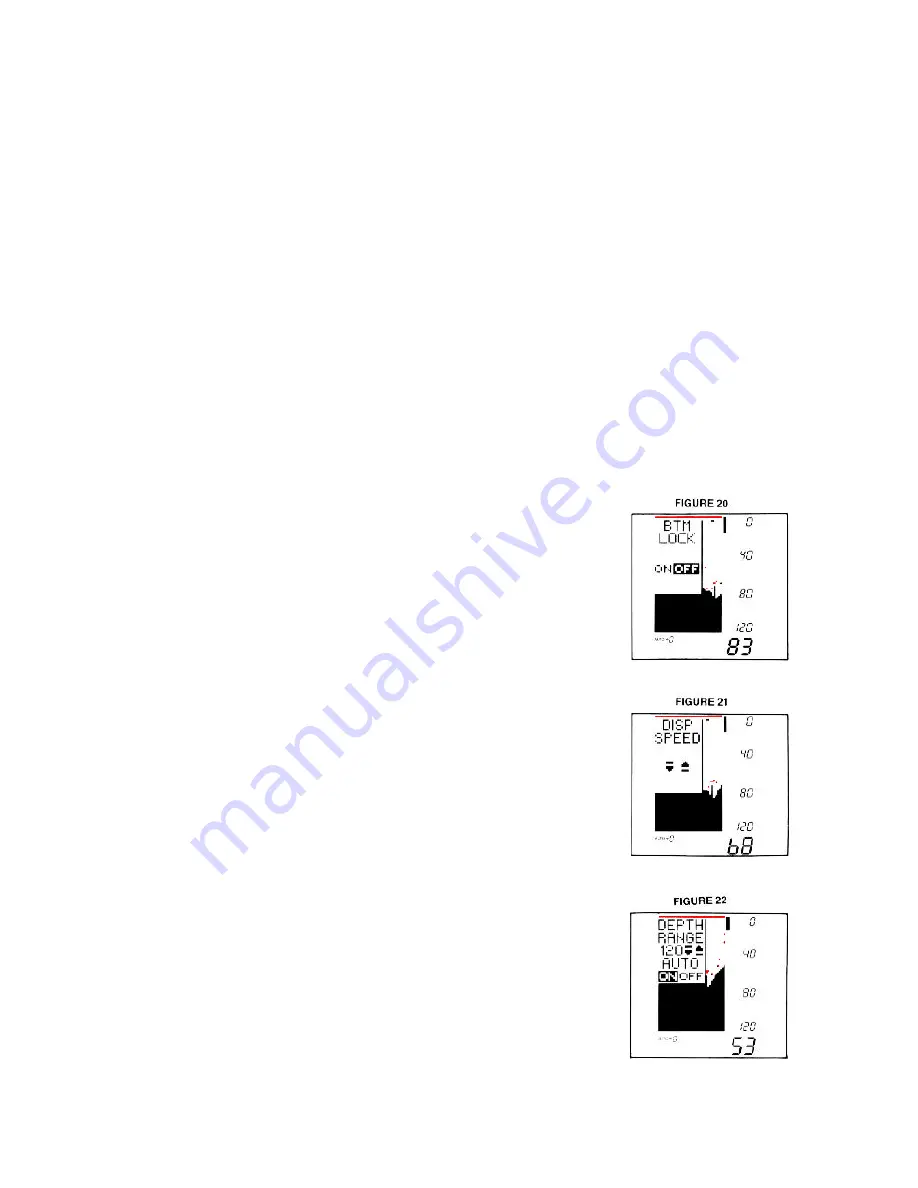
Bottom-Lock
Automatic setting: off
You can easily turn on the bottom-lock with the On/Off button.
When on, this function shows up-close zoom readings in
reference to the bottom. The size of the zoom window
depends on the depth range - 7½ feet in the 15' and 30'
ranges, and 15 feet in the 60’ and 120' ranges. The zoom
window will automatically move up or down to stay on the
bottom, with the cursor showing you the portion of the total
depth range that is being displayed. This is an ideal feature for
finding structure or locating fish near the bottom.
6.
Display Speed
Automatic setting: one setting less than highest speed
The speed at which the TCR display moves depends on the
display speed setting, and it is easily changed by pressing the
Up arrow for a faster setting and the Down arrow for a slower
setting. Generally speaking, the higher speed settings allow
faster updates while slower display speeds provide more
information.
Summary of Contents for TCR ID-1
Page 1: ......


