background image

3

Introduction

Accessories:

 Additional recommended accessories include a Heading Sensor GPS 

Puck, a Heading Sensor GPS Adapter (APEX/SOLIX only), and transducer extension 
cables. For the most current list of compatible accessories, visit our Web site at 

humminbird.com.


Supplies

In addition to the hardware included with your accessory, you will need the following 
supplies:

•  Cable ties for cable routing

•  1 Amp fuse

•  Level 

•  Pencil

•  Marine-grade silicone sealant (optional)

•  Anti-seize tube

If you purchased a model with a GeigerTec mounting bracket included, the following 
supplies are recommended:

•  Powered hand drill

•  1/4" drill bit 

•  Hex key

•  Hex socket wrench or nut driver

•  (4) stainless steel 1/4" - 20 bolts with a flat or oval head (select a length 

appropriate for your deck thickness)

•  (4) stainless steel 1/4" fender washers (recommended)

•  (4) stainless steel 1/4" - 20 nylon insert hex nuts

Switch (optional):

 If you do not have a main switch or fuse panel available on your 

boat to connect power, you will need to purchase a battery switch. See 

Route the 

Cables and Connect Power

 for more information.

Summary of Contents for MEGA 360 UNIVERSAL

Page 1: ...1 MEGA 360 UNIVERSAL INSTALLATION GUIDE 532750 3EN_A ...

Page 2: ...hallow water or submerged objects WARNING The electronic chart in your Humminbird unit is an aid to navigation designed to facilitate the use of authorized government charts not to replace them Only official government charts and notices to mariners contain all of the current information needed for the safety of navigation and the captain is responsible for their prudent use WARNING Humminbird is ...

Page 3: ...responsible for incorrect translations or discrepancies between documents NOTE Product specifications and features are subject to change without notice NOTE Humminbird verifies maximum stated depth in saltwater conditions however actual depth performance may vary due to transducer installation water type thermal layers bottom composition and slope 360 Imaging APEX Cannon CoastMaster HELIX Humminbi...

Page 4: ... the Universal Boat Mount 9 A Direct Installation 9 B Cannon Mounting Track Installation separate purchase 11 3 Install the MEGA 360 Imaging Pod 11 4 Adjust the Pod Height and Install the Depth Collar 12 Route the Cables and Connect Power 14 Set Up the Control Head 17 1 Confirm Connections 17 2 Set Up the Transducer 19 3 Test MEGA 360 Imaging on the Control Head 20 4 Add Offset Features to the MEG...

Page 5: ...ransducer Maintenance 26 Troubleshooting 27 Fishing System Doesn t Power Up 27 Fishing System Defaults to Simulator with a Transducer Attached 28 Finding the Cause of Noise 29 Specifications 30 Contact Humminbird 32 Table of Contents ...

Page 6: ...iii ...

Page 7: ...h this installation the Humminbird fish finder should be installed Compatibility Fish Finders MEGA 360 Imaging Universal is compatible with the following Humminbird fish finders APEX Series SOLIX Series G2 and G3 models HELIX MEGA Imaging G3N and G4N models NOTE You must have a GPS heading sensor compass installed in order to use the MEGA 360 Imaging navigation features NOTE MEGA 360 Imaging can b...

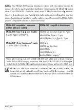
Page 8: ... Transducer Y cable 9 M360 2DDI Y 720107 1 HELIX Dual Spectrum Type 9 7 pin HELIX MDI Type 9 7 pin HELIX MDI MSI Type 9 7 pin MEGA 360 14 pin Transducer Y cable 14 M360 2DDI Y 720108 1 APEX MSI SOLIX Dual Spectrum SOLIX MDI SOLIX MDI MSI Built in MEGA Imaging If this cable is being used with a HELIX G3N G4N with MEGA Side or Down Imaging and a Built in MEGA imaging transducer then the 720109 1 AD ...

Page 9: ... silicone sealant optional Anti seize tube If you purchased a model with a GeigerTec mounting bracket included the following supplies are recommended Powered hand drill 1 4 drill bit Hex key Hex socket wrench or nut driver 4 stainless steel 1 4 20 bolts with a flat or oval head select a length appropriate for your deck thickness 4 stainless steel 1 4 fender washers recommended 4 stainless steel 1 ...

Page 10: ...l to review the software version number that is currently installed on the control head and each accessory APEX Series 1 Press the HOME key 2 View the Software Version listed under System Info in the Data Dashboard SOLIX Series 1 Press the HOME key 2 Select Settings 3 Select Network Network Info 4 The Network Info dialog box shows a section for each device connected to the network Scroll to each s...

Page 11: ...rmatted SD or microSD card into the computer card slot 3 Go to humminbird com and click Support Software Updates 4 Click on your control head model The available software updates are listed as downloads under each product Confirm the file name is for your control head model Read the notices and instructions and select Download Follow the on screen prompts to save the software file to the SD or mic...

Page 12: ...oSD card 4 Power on your Humminbird control head Start Normal mode 5 Insert the SD or microSD card with the software file into the control head card slot 6 APEX SOLIX Select the Files tool From the Software Update tab scroll to MEGA 360 on the Accessories list Confirm that the most current software version is selected from the list and select Install Now HELIX The software will be automatically de...

Page 13: ...p the System menu icon Google Android Tap the FishSmart main menu Select system 3 Tap Update next to the selected unit The download progress is displayed on the screen 4 Tap Transfer next to the selected unit once the download is complete 5 Confirm the estimated transfer time 6 Tap the checkbox to select where to upload the software update internal storage card slot 1 or card slot 2 NOTE For APEX ...

Page 14: ...ead Test run the power cable from the chosen mounting location to the main switch or fuse panel Determine whether you will need to purchase extension cables It is important to consider the following The MEGA 360 Imaging transducer pod is powered separately from the control head It must be connected to a switch where it can be powered on when the boat is underway and powered off when it is docked T...

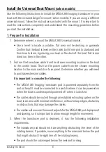
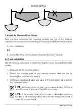
Page 15: ...ec mount included with select models 1 Clean and dry the mounting surface 2 Position the mounting plate in your selected location Mark the four 4 mounting bolt locations with a pencil 3 Set the universal bracket aside and use a 1 4 6 35 mm drill bit to drill the four 4 marked holes NOTE On fiberglass hulls it is best to use progressively larger drill bits to reduce the chance of chipping or flakin...

Page 16: ...lant separate purchase required to both bolts and drilled holes as needed to protect your boat from water damage 5 From under the deck or gunwale install the 1 4 fender washer and the 1 4 20 nylon insert hex nut not included onto each screw Hand tighten only Use an adjustable socket or wrench to hand tighten the nuts until they contact the washers Then tighten the nuts an additional 2 full revolut...

Page 17: ... endcap 2 Slide the GeigerTec mount into the track and to the desired position 3 Insert the included thumb screws into the screw holes in the dual purpose base 4 Hand tighten the thumb screws so that the base cannot shift inside the track 3 Install the MEGA 360 Imaging Pod 1 Route the cables and pod shaft up through the universal boat mount NOTE It will be a tight fit over the rubber plug at the t...

Page 18: ...12 Installing the Mount 4 Adjust the Pod Height and Install the Depth Collar 1 Loosen the bracket arms and rotate the bracket so that the MEGA 360 pod is positioned over the water Adjusting the Bracket ...

Page 19: ... 4 from the top of the shaft 4 Use hex key to tighten the depth set collar Hand tighten only 5 Turn the pod shaft until the rounded end of the transducer points in the direction of travel The centerline of the transducer should be parallel with the centerline of the boat See the illustration Aligning the Transducer rounded part of transducer Aligning the Transducer 6 When the transducer position i...

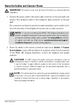
Page 20: ... at www humminbird com support installation diagrams to view the wiring diagrams 2 Route the cables to the chosen connection locations in Section 1 Prepare for Installation Leave sufficient slack in the cables to allow for full movement of the MEGA 360 Imaging transducer in both the deployed and stowed positions CAUTION Do NOT mount the cables where the connectors could be submerged in water or fl...

Page 21: ...nel usually located near the console If you must connect to a battery connect to a battery switch not included WARNING The MEGA 360 Imaging transducer should be connected to a main switch fuse panel or battery switch Humminbird does not recommend connecting to a battery without a fuse and a switch CAUTION Some boats have 24 or 36 Volt electric systems but the MEGA 360 Imaging transducer MUST be co...

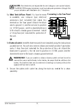
Page 22: ...r protection of the unit OR 5b Battery Switch Install the battery switch not included using the instructions provided with it You will also need to obtain and install an inline fuse holder and a 1 Amp fuse not included for the protection of the unit Attach the black wire to ground the red wire to positive 12 VDC power and the drain shield wire to the boat s chassis ground terminal WARNING If you a...

Page 23: ...2 On the control head press and hold the POWER key If you are powering on a control head in a multiple control head Ethernet network power on the control head that is connected to the MEGA 360 Imaging transducer first 3 Select Normal mode 4 Review the status bar in the top right corner of the screen to confirm the sensor status for the MEGA 360 Imaging transducer is connected MEGA 360 Status Icon ...

Page 24: ...on a control head in a multiple control head Ethernet network power on the control head that is connected to the MEGA 360 Imaging transducer first 3 When the Title screen is displayed press the MENU key 4 Select Normal Press the RIGHT Cursor key 5 Press and hold the VIEW key Select System Accessory Test Confirm that MEGA 360 Imaging is listed as Connected NOTE If the Accessory Test is not displaye...

Page 25: ...l and select CHIRP Sonar Sonar Source HELIX Series Use the following instructions to select the connected transducer for your control head These steps are only required the first time you set up your HELIX control head with a new transducer 1 Main Menu Press the Menu key twice 2 Select the Sonar tab Connected Transducer 3 Press the RIGHT or LEFT Cursor keys to scroll through the compatible transdu...

Page 26: ... Tap the View widget icon in the side bar NOTE Once the MEGA 360 has been detected the first time the 360 Imaging view will display on the Favorite Views widget 2 Tap 360 Imaging 3 The sonar returns from the MEGA 360 scan will begin to display on the MEGA 360 View Review the display for the following information and see the illustration Reviewing the 360 View Bottom Confirm that the bottom is visi...

Page 27: ...ottom Confirm that the bottom is visible on screen Blocked Beams If the beams hit a hard surface it will appear as bright white on the display If the beams are blocked by any objects move the objects if possible You can also adjust the 360 Range on the X Press Menu to see more or less detail on the display In some cases the trolling motor will appear on the display as a shadow 4 Stop Pinging When ...

Page 28: ...alignment of the MEGA 360 Imaging display For example if there is an object in the water that is displayed on the left side of the MEGA 360 View but you can see that it is straight ahead you can use this setting to rotate the display NOTE This menu option should be adjusted while the MEGA 360 Imaging transducer is pinging APEX SOLIX Series 1 With a MEGA 360 View displayed on screen tap Sonar 360 i...

Page 29: ...ress the CHECK INFO key to confirm your setting The zero point on the display is represented by a green line MEGA 360 Imaging Heading Offset HELIX 360 heading offset angle 5 Set up the Network After you have confirmed all connections the MEGA 360 Imaging transducer is ready to use on the water Proceed to your MEGA 360 Operations Manual to set up the depth source temperature source and additional s...

Page 30: ...tery switch Powering off the MEGA 360 Imaging transducer will be determined by the installation and power connection on your boat Travel with the Pod Installed The pod must not hit the deck base or any objects This is critical during transport For models with the GeigerTec mount Loosen the bracket arms and rotate the bracket so that the MEGA 360 pod is safely stowed along the deck or gunwale Check...

Page 31: ...58 F 40 C to 70 C dry conditions If the MEGA 360 pod becomes clogged with debris you may remove the guard ring to clean around the pod 1 Remove the 3 screws on the guard ring 2 Pull the guard ring straight off the pod The guard ring is keyed to fit over the screw holes so do not twist it off 3 Gently clean the MEGA 360 pod of debris You can use mild soap and warm water 4 Replace the guard ring and...

Page 32: ...o contact with salt spray wipe the affected surfaces with a cloth dampened with fresh water Transducer Maintenance Use the following information to maintain the transducer operation If your boat remains in the water for long periods of time algae and other marine growth can reduce the effectiveness of the transducer Periodically clean the face of the transducer with a cloth dampened with fresh wat...

Page 33: ...on guide that is included with your Fishing System to confirm specific details making sure that the power cable is properly connected to the Fishing System control head the power cable is wired correctly with red to positive battery terminal and black to negative terminal or ground and the drain shield wire to the boat s chassis ground terminal the fuse is operational and the battery voltage of th...

Page 34: ...control head is not detecting the transducer Perform the following troubleshooting tasks Check the connections of all transducers that are connected to the control head or Ethernet network See the transducer installation guide that was included with your Fishing System for connection information Review this MEGA 360 Imaging installation guide to confirm that the transducer cable is connected corre...

Page 35: ...rs Other sonar devices Turn off any nearby sonar devices to see if the problem goes away then turn them on one at a time to see if the noise re appears The boat s engine To determine whether the boat s engine is the source of the noise increase the RPMs whiletheboatisinneutralandstationaryto see if the noise increases proportionately if noise appears when you rev the engine the problem could be th...

Page 36: ...urrent Draw 0 5 A maximum Operating Temperature 4 F to 158 F 20 C to 70 C Storage Temperature 40 F to 158 F 40 C to 70 C NOTE Humminbird verifies maximum stated depth in saltwater conditions but actual depth performance may vary due to transducer installation water type thermal layers bottom composition and slope NOTE Product specifications and features are subject to change without notice ...

Page 37: ... disposal during the product life cycle WEEE compliance may not be required in your location for electrical electronic equipment EEE nor may it be required for EEE designed and intended as fixed or temporary installation in transportation vehicles such as automobiles aircraft and boats In some European Union member states these vehicles are considered outside of the scope of the Directive and EEE ...

Page 38: ...dfish Instagram com humminbirdfishing YouTube com humminbirdtv Contact Humminbird Contact Humminbird Technical Support through our Help Center at https humminbird help johnsonoutdoors com hc en us or in writing to the address below Humminbird Service Department 678 Humminbird Lane Eufaula AL 36027 USA ...

Reviews: