background image

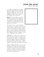
depth of the water changes, the range
changes as necessary in order to retain
a bottom representation on-screen. 

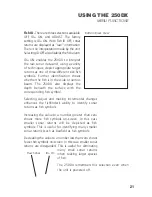
When in Auto mode, the horizontal
line at the top of the screen is the
“zero line,” representing the surface
of the water. Occasionally there is a
gap in this line. This gap indicates the
unit is updating the display even if
the bottom is not visible on-screen,
or if the bottom information is not
changing.

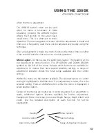
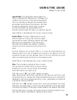
New sonar information appears on
the right side of the graphic area of
the display and moves to the left as
new information is displayed. The
250DX automatically selects the appropriate depth range to show the
depth of water beneath the transducer. This range is selected so the
bottom representation is typically shown about 

²⁄₃

down the display.

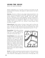
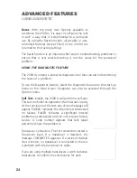
Bottom.

The graphic depiction of the

bottom provides an effective tool for
understanding the composition of
the bottom. If the bottom is hard and
smooth, the bottom depiction is
narrow and dense. If the bottom is
soft mud or sand, the depiction will
be thick and less dense. This indicates
much of the signal is absorbed by the
soft bottom. If the bottom is rocky or
rugged in composition, the depiction
is of varying density and textured in
appearance.

Wave action also affects the bottom
depiction. The information drawn is a

9

USING THE 250DX

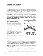
WHAT YOU SEE ON-SCREEN

Water Depth

Bottom Depiction

Depth Range

Figure B

Zero Line

Surface Clutter     Rocky Bottom

Soft Bottom     Hard Bottom

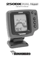
Summary of Contents for DUAL BEAM 250DX

Page 1: ...Operations Manual ...

Page 2: ... your purchase and help us learn more about you please fill out the warranty registration card at the back of this manual WARNING This device should not be used as a navigational aid to prevent collision grounding boat damage or personal injury When the boat is moving water depth may change too quickly to allow time for you to react Always operate the boat at very slow speeds if you suspect shallo...

Page 3: ...ting Methods 4 Transducer Exchange 5 USING THE 250DX 6 How Sonar Works 6 Simulator Operation 7 What You See On Screen 8 Control Functions 11 Menu Functions 14 ADVANCED FEATURES 24 Using Diagnostic 24 MAINTENANCE 25 Maintenance 25 Troubleshooting 26 Customer Support 30 Specifications 31 TABLE OF CONTENTS REV 10822E ...

Page 4: ...sories available and ordering information All Humminbird accessories are available through your full service Humminbird dealer or factory direct through our number listed in the Customer Support section INSTALLATION OVERVIEW The 250DX consists of two primary components to install the control head and the transducer The control head contains the sonar transmit and receive circuitry as well as the u...

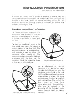
Page 5: ...he transducer on the outside of the boat hull This technique produces the least signal loss and provides a way to adjust the transducer after installation The mounting hardware included is designed to protect both the boat and the transducer should the boat strike debris in the water or when trailering As an alternative to transom mounting it is possible on many fiberglass hulled boats to glue the...

Page 6: ... The standard transducer can be adapted for portable installations using part number MHX PT2 This accessory adapts your transducer to a suction cup mount for temporary installation on the boat hull or other surface Trolling Motor Mounting The standard transducer can also be adapted to mount on most trolling motors using part number AD STM 7 This accessory includes a bracket and hose clamp that all...

Page 7: ...rmation BEGINNING INSTALLATION Now that you have determined the transducer mounting method you can begin installation of the 250DX The fold out installation guide included provides detailed step by step instructions for installation of the control head and transducer For transom mount transducer installations you will need the mounting template at the front of this manual In addition to the parts ...

Page 8: ...e 250DX is a dual frequency dual beam unit and generates two distinct sonar signals one narrow one wide Each signal is optimized for a particular purpose First the center beam transmits at a frequency of 200 kHz in a 20 degree narrow symmetrical pattern for greater depth capability and excellent detail Information from this center beam is used to draw the graphic representation of the bottom on th...

Page 9: ...ter you power up the unit When this screen is shown simply press the DOWN ARROW until Simulator is highlighted When the screen times out the unit will be in simulator mode When in simulator operation the 250DX responds to control inputs as if it is in actual operation so feel free to experiment or to customize the unit for your particular operation To exit Simulator mode power the unit off When in...

Page 10: ...p the 250DX uses settings that were set at the factory After initial use the 250DX will remember the settings you enter There are several elements on screen that are common to all modes of operation Temperature Speed The initial screen layout takes one of two basic forms depending on whether the optional Temp Speed accessory is installed Figure A shows the default view when the Temp Speed accessor...

Page 11: ...show the depth of water beneath the transducer This range is selected so the bottom representation is typically shown about down the display Bottom The graphic depiction of the bottom provides an effective tool for understanding the composition of the bottom If the bottom is hard and smooth the bottom depiction is narrow and dense If the bottom is soft mud or sand the depiction will be thick and l...

Page 12: ...wind or wave action This area of water interferes with sonar transmission and often appears on screen as regular clusters of individual dots near the 0 line Thermoclines Thermoclines are sharp differences in water temperature These are easily identified by the continuous nature of the return Second Returns When a sonar signal is reflected off the bottom back to the transducer there is often enough...

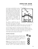
Page 13: ...ths or for downrigger operation The fish symbols indicate the sonar beam the fish is detected in This gives you a reliable indicator of side to side location of the fish relative to the boat Fish symbols that are hollow are detected in the wide beam and are around the boat Solid fish symbols represent fish detected in the narrow beam and are directly under the boat CONTROL FUNCTIONS The 250DX uses...

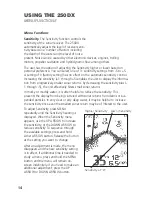
Page 14: ... pressing MENU repeatedly cycles through all available menu headings When a menu heading displays the full menu appears after a short pause A menu remains on screen for several seconds and can be adjusted by using the ARROW keys If no adjustment is made in the allotted time the menu disappears If you want the menu to remain on screen longer press and hold MENU the menu will remain on screen indefi...

Page 15: ... menu indicate which buttons are available for adjustment In menus that have several possible settings a range of adjustment indicator shows the total range available and the current setting Within the menu are the options available The selected option or current setting is highlighted in the black box If no adjustment is made this is the selected setting Press an ARROW button while the menu is di...

Page 16: ...ns In murky or muddy water it is often helpful to reduce the sensitivity This prevents the display from being cluttered with sonar returns from debris or sus pended particles In very clear or very deep water it may be helpful to increase the sensitivity since even the smallest sonar return may be of interest to the user To adjust Sensitivity press MENU repeatedly until the Sensitivity heading is d...

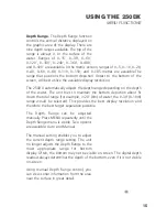
Page 17: ...tries to maintain the bottom depiction about down the total range for example in 20 6m of water the 0 30 0 10m range would be selected This provides the best display resolution and therefore the best target separation possible The Depth Range can be adjusted manually Press MENU repeatedly until the Depth Range menu is visible Two options are available Auto and Manual The manual setting enables you...

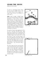
Page 18: ... ranges available 2m 7 5m 15 10m 30 and 20m 60 These ranges are not directly user controlled but are instead dependent on the current depth range In shallow water when the 5m 15 or 10m 30 range is in use the Zoom range is 2m 7 If the 20m 60 or 40m 120 range is in use the Zoom range is 5m 15 if a 60 150m 180 480 depth range is in use the Zoom range is 10m 30 and if the 185m 600 range is in use the ...

Page 19: ...ater and the lower number can never be greater than the active depth range The difference between the two numbers the Zoom range is preset and determined by the active depth range Once manual Zoom is selected the display appears the same as in Auto Zoom but the zoom range does not change automatically To disable Zoom press the MENU button until the Zoom menu is on screen Use the UP ARROW to highli...

Page 20: ... on input from the Temp Speed sensor Since Triplog requires information from the Temp Speed sensor to operate if this sensor is not detected by the 250DX the Triplog menu will not appear as an option Triplog provides seven pieces of information the current digital depth water surface temperature current boat speed the distance traveled since the 250DX was powered up or reset the average speed the ...

Page 21: ...peration There are thirteen Option menus Contrast Display Speed Battery Alarm Bottom Black Fish ID Numeral Size Diagnostic Units Languages Speed Offset Depth Offset Filter and Reset Contrast The Contrast function allows the user to control the level of contrast of the LCD display The 250DX will automatically adjust the display contrast to compensate for changing ambient temperatures however some s...

Page 22: ...h the DOWN ARROW BUTTON to select the feature ON Push the DOWN ARROW BUTTON again to move into the ADJUST BATTERY ALARM setting Using the UP and DOWN ARROW BUTTONS select a voltage between 9 0 and 12 0 When the voltage drops below your selected voltage an audible alarm will sound and a battery alarm icon will be displayed on screen with current voltage level Bottom Black There are two selections a...

Page 23: ...the corresponding fish symbol Selecting Adjust and making incremental changes enhances the fishfinder s ability to identify sonar returns as fish symbols Increasing the value to a number greater than zero shows more fish symbols on screen In this case smaller sonar returns will be depicted as fish symbols This is useful for identifying many smaller sonar returns such as baitfish as fish symbols De...

Page 24: ...HIDE Selecting SHOW brings up the Diagnostic screen See the Using Diagnostic section for more information Units The Units function allows the user to select the units of measurement for the depth and speed readout Metres KTS metres nautical miles per hour Metres KPH metres kilometres per hour FEET MPH feet statute miles per hour and FEET KTS feet nautical miles per hour are available The 250TX rem...

Page 25: ...er location and the deepest point of the hull will have the same effect as mounting the transducer at the deepest point Depth offset is remembered after power is disconnected Filter Filter provides an advanced level of control over the amount of detail visible on screen and the sensitivity of the unit You can choose the setting s that works best for your style of use With Filter set to OFF the 250...

Page 26: ... initial screen Diagnostic can also be accessed through the Options menu Self Test Initially the 250DX will perform a self test This test confirms the operation of all internal circuitry At the conclusion of the test one of two messages will appear PASSED indicates the internal test discovered no failures FAILED indicates a significant internal problem was discovered and the unit requires factory ...

Page 27: ...ic while running the boat at high speeds to show the voltage gain Also if you are using the 250DX in portable configuration or from the trolling motor battery Diagnostic can be used to evaluate the health of the battery by showing the current voltage Total Time The total time category indicates the total time the unit has been in use since shipped from the factory It is normal for some hours to ap...

Page 28: ...ed in hot weather can damage the electronics TROUBLESHOOTING Do not attempt to repair the 250DX yourself There are no user serviceable parts inside and special tools and techniques are required for reassembly to ensure the waterproof integrity of the housing Repairs should be performed only by authorized Humminbird technicians Many requests for repair received by Humminbird involve units that do n...

Page 29: ...ator operation is possible First ensure that an appropriate transducer connector is positioned correctly in the connector holder and that the unit is fully seated on the mount The 250DX will work with the standard tri beam transducer Second inspect the transducer cable from end to end for breaks kinks or cuts in the outer casing of the cable Also ensure the transducer is fully submerged in water I...

Page 30: ...t digital depth indication The 250DX will work reliably in water 1m 3 or deeper The depth is measured from the transducer not necessarily from the surface 5 The unit comes on before I press POWER and won t turn off Check the transducer cable if the outer jacket of the cable has been cut and the cable is in contact with bare metal you need to repair the cut with electrical tape If there is no probl...

Page 31: ...n input voltages below 10 VDC 9 The display shows many black dots at high speeds and high sensitivity settings You are seeing noise or interference caused by one of several sources Noise can be caused by other electronic devices Turn off any nearby electronics and see if the problem goes away Noise can also be caused by the engine If engine noise is causing the interference the problem will intens...

Page 32: ...AINTENANCE CUSTOMER SUPPORT CUSTOMER SUPPORT If you have any problems or questions with your Humminbird unit contact your local distributor Humminbird Service Department 108 Maple Lane Eufaula AL 36027 USA ...

Page 33: ... FSTN LCD LCD Matrix 128 V x 64 H Pixels Viewing Area 2 90 V x 2 35 H 7 3cm V x 5 97cm H Mounting Quick Disconnect Mount Unit Size 6 H x 6 W x 4 D 17 1cm H x 15 9 cm W x 10 5 cm D Transducer Standard XT 6 20 Transducer Cable Length 20 6 metres Depth Ranges 15 30 60 120 180 240 360 480 600 5 10 20 40 60 80 110 150 185 metres Zoom Ranges 7 15 30 60 2 5 10 20 metres SPECIFICATIONS ...

Page 34: ...on PLACE EITHER CORNER ON DEADRISE ANGLE TOP Use 4 0mm drill bit Drill Drill Use with XT series Transducers Fiberglass Alumium Drill a set of two holes for your type of boat hull Use the upper set for fiberglass or the lower set for aluminum ...

Page 35: ...P N 530975 2 ...

Page 36: ......

Reviews: