background image

12

frequently used menu can be adjusted very quickly using this technique.

After an adjustment is made to a menu function, the menu times out after
a few seconds and the unit returns to normal operation. 
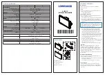
Menu Layout.

All menus use the same basic layout. The heading at the

top describes the menu function. The UP ARROW and DOWN ARROW
symbols to the left of the menu indicate which buttons are available for
adjustment. In menus that have several possible settings, a range of
adjustment indicator shows the total range available and the current
setting. 

Within the menu are the options available. The selected option or current
setting is highlighted in the black box. If no adjustment is made, this is the
selected setting. Press an ARROW button while the menu is displayed to
select another option.

Several of the menus are multi-step. In some situations if an adjustment is
made, additional options become available for further adjustment.
Examples of these multi-step menus are Depth Range, Depth Alarm and
Zoom. See the detailed description of each function for further
explanation.

Menu Functions

Sensitivity.

The Sensitivity function controls the sensitivity of the sonar

receiver. The 150SX automatically adjusts the level of receiver sensitivity
based on a number of factors including the depth of the water and the
level of noise present. Noise can be caused by other electronic devices,
engines, trolling motors, propeller cavitation and hydrodynamic flow
among others.

The user has the option of adjusting the Sensitivity higher or lower based

USING THE 150SX

MENU FUNCTIONS

Heading

Up Arrow Option

Down Arrow Option

Arrow Symbols

Selected Setting

Range of Adjustment Indicator

Summary of Contents for 150SX

Page 1: ...Operations Manual...

Page 2: ...one year period Complete details are included at the end of this manual We encourage you to read this operations manual carefully in order to get full benefit from all the features and uses of your H...

Page 3: ...4 Transducer Exchange 5 USING THE 150SX 6 How Sonar Works 6 Simulator Operation 6 What You See On Screen 8 Control Functions 10 Menu Functions 12 ADVANCED FEATURES 20 Using Diagnostic 20 MAINTENANCE A...

Page 4: ...ION OVERVIEW The 150SX consists of two primary components to install the control head and the transducer The control head contains the sonar transmit and receive circuitry as well as the user controls...

Page 5: ...oss and provides a way to adjust the transducer after installation The mounting hardware included is designed to protect both the boat and the transducer should the boat strike debris in the water or...

Page 6: ...metal hulls and sail boats create unique transducer mounting needs Alternate transducers and mounting methods are detailed below Portable Mounting The standard transducer can be adapted for portable i...

Page 7: ...included provides detailed step by step instructions for installation of the control head and transducer For transom mount transducer installations you will need the mounting template at the back of t...

Page 8: ...ck again in less than of a second It is unlikely that your boat can outrun this sonar signal The 150SX is a 200 kHz single beam fishfinder The 200 kHz frequency provides excellent sonar resolution the...

Page 9: ...the word simulator occasionally scrolls across the display indicating the information on screen is not real sonar data FEATURE MEMORY If your 150SX is installed with a transducer connected any change...

Page 10: ...est match the depth of the water As the depth of the water changes the range changes as necessary in order to retain a bottom representation on screen When in Auto mode the horizontal line at the top...

Page 11: ...ptimized to give the most accurate depiction of bottom structure possible Grass trees stumps wrecks or other debris are accurately displayed however the depiction of these objects varies with boat spe...

Page 12: ...have different sonar characteristics so it is not always possible to distinguish fish size between varying species The signal intensity is normalized for depth so that a small fish close to the boat d...

Page 13: ...al operation pressing MENU repeatedly cycles through all available menu headings When a menu heading displays the full menu appears after a short pause A menu remains on screen for several seconds and...

Page 14: ...on while the menu is displayed to select another option Several of the menus are multi step In some situations if an adjustment is made additional options become available for further adjustment Examp...

Page 15: ...u appears use the UP ARROW to increase the sensitivity or the DOWN ARROW to reduce sensitivity To sequence through the available settings press and hold either ARROW button Release the button at the s...

Page 16: ...Using manual Depth Range control you can view sonar information from the area near the surface in great detail To return to automatic Depth Range control press the MENU button until the Depth Range m...

Page 17: ...to select either AUTO or MANUAL While using Automatic Zoom the depth adjustment is controlled automatically allowing you to view the area immediately above the bottom This is especially useful if you...

Page 18: ...large fish symbols The 150SX can be set to alarm on only large and medium fish or set to alarm on all fish Once the Fish Alarm is enabled the 150SX emits an audible beep when the selected size fish sy...

Page 19: ...the graphic information moves across the display There are 5 possible speeds the fastest rate 5 is the factory setting Keep in mind that the closer the update rate matches your boat speed the more ac...

Page 20: ...gives the user easiest recognition of the bottom location even from a great distance The 150SX remembers the Bottom Black setting when powered off Fish ID ID ON enables the 150SX to interpret the raw...

Page 21: ...and speed and temp numerals are drawn large enough to be read from across the boat The big numerals occupy space on the display that could be used for the graphics area Hence the small numerals option...

Page 22: ...pth offset is to show the depth beneath the deepest point of the hull A negative value equal to the distance from the transducer location and the deepest point of the hull will have the same effect as...

Page 23: ...irm the connections for each Voltage Input Another connection tested is the voltage input and is especially helpful in diagnosing input voltage problems The current input voltage is displayed If volta...

Page 24: ...Pivoting the transducer up in the bracket may allow better access for inspection or cleaning If your boat remains out of the water for a long period of time it may take some time to wet the transducer...

Page 25: ...s reversed the unit will not work Examine the contacts on the back of the unit to ensure there is no corrosion Finally ensure the unit is firmly seated on the mount The electrical contacts are not mad...

Page 26: ...cable from end to end for breaks kinks or cuts in the outer casing of the cable If the transducer is connected to the unit through a switch temporarily connect it directly to the unit and try again If...

Page 27: ...over a wide range of input voltages SureVolt from Humminbird is a recommended unit providing 12 VDC out with inputs from 6 VDC to 23 VDC 8 The screen begins to fade out Images are not as sharp as nor...

Page 28: ...el Post shipping back to the customer free of charge This warranty applies to the original purchaser only This warranty is in lieu of all other warranties expressed or implied and no representatives o...

Page 29: ...LCD LCD Matrix 128 V x 64 H Pixels Viewing Area 2 90 V x 2 35 H 7 3cm V x 5 97cm H Mounting Quick Disconnect Mount Unit Size 6 H x 61 W x 4 D 17 1cm H x 15 9 cm W x 10 5 cm D Transducer Standard XHS...

Page 30: ......

Page 31: ...Remove and use for Transducer Installation DO NOT LET DEADRISE INTERSECT THIS LINE PLACE EITHER CORNER ON DEADRISE ANGLE TOP Use 5 32 drill bit Drill Drill For use with bracket PN 404329 1...

Page 32: ......

Page 33: ......

Page 34: ......

Page 35: ...P N 530974 2...

Page 36: ......

Reviews: