background image


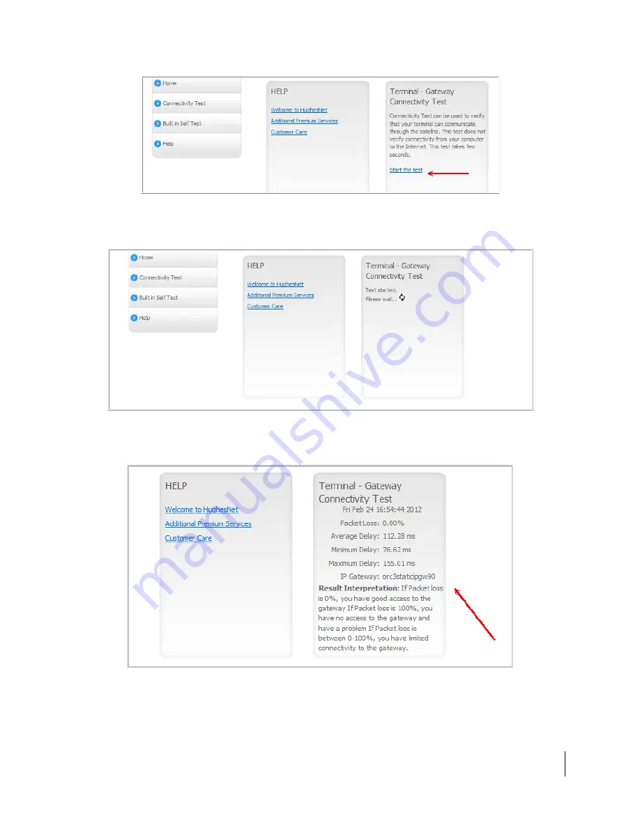
Figure 11:  Connectivity Test start screen 

The Terminal - Gateway Connectivity Test panel appears indicating the test has 

started, as shown in Figure 12. 


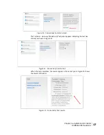
Figure 12:  Connectivity Test started 

When the test completes, the results appear in the center panel. Figure 13 shows 

the results of the test. 


Figure 13:  Connectivity Test results 

Chapter 2 ● System Control Center 

1039650-0001 Revision A 

17 


Summary of Contents for Jupiter HT1100

Page 1: ...HT1100 Satellite Modem User Guide 1039650 0001 Revision A July 1 2013 11717 Exploration Lane Germantown MD 20876 Phone 301 428 5500 Fax 301 428 1868 2830 ...

Page 2: ...ort to ensure the correctness and completeness of the material in this document Hughes Network Systems LLC shall not be liable for errors contained herein The information in this document is subject to change without notice Hughes Network Systems LLC makes no warranty of any kind with regard to this material including but not limited to the implied warranties of merchantability and fitness for a p...

Page 3: ...nts 9 Networking requirements 9 Internet browser 9 Contact information 9 Chapter 2 System Control Center 11 Accessing the System Control Center 11 System Control Center home page 11 Indicator links 12 Parameters bar 14 Center panel text links and information 14 Side panel 14 System Status page 15 System Information page 16 Connectivity Test 16 Built In Self Test 18 HELP 18 Chapter 3 LEDS 21 Append...

Page 4: ......

Page 5: ...h of these signal words indicates the severity of the potential hazard DANGER indicates a potentially hazardous situation which if not avoided will result in death or serious injury WARNING indicates a potentially hazardous situation which if not avoided could result in death or serious injury CAUTION indicates a potentially hazardous situation which if not avoided could result in minor or moderat...

Page 6: ...ls may appear next to DANGER WARNING or CAUTION to indicate a specific type of hazard for example fire or electric shock If other hazard symbols are used in this document they are identified in this section Additional symbols This document uses the following hazard symbols Indicates a safety message that concerns a potential electric shock hazard 6 Understanding safety alert messages 1039650 0001 ...

Page 7: ...rk to provide Internet service The modem has an Ethernet port so it can be connected to a computer or LAN Figure 1 shows the front of the HT1100 satellite modem After your HT1100 satellite modem has been installed you can use your computer s web browser to access the Internet or an intranet The HT1100 supports local area networks LANs to extend Internet connectivity to multiple computers This requ...

Page 8: ...ctivated with a small software update Hughes does not recommend plugging anything into this port at this time Hughes will inform you when this feature is available Operating environment Observe the following requirements for the modem s operating environment Ventilation and heat sources The modem must be adequately ventilated and kept away from sources of heat 8 Chapter 1 Overview 1039650 0001 Rev...

Page 9: ... NIC 10 100 1000 Mbps configured as follows Auto negotiate Dynamic host configuration protocol DHCP enabled obtain an IP address automatically Internet browser Internet Explorer 7 or greater Mozilla Firefox Safari for Windows and Mac Browser settings HTTP 1 1 or greater enabled Proxy settings disabled Contact information If you need operational warranty or repair support who you should contact dep...

Page 10: ...e a In the Contact Hughes section click Email b Complete the email form c Click Email Us 3 Chat with a Customer Care representative a In the Contact Hughes section click Chat b Complete the chat form c Click Chat with Us 4 Call a Customer Care representative If these options do not help you call Hughes Customer Care at 1 866 347 3292 For modems purchased from a value added reseller VAR in the Unit...

Page 11: ...the satellite modem s LAN port The System Control Center web site is hosted on the modem consequently the computer does not have to be connected to the Internet To open the System Control Center double click the System Control Center shortcut on your computer desktop or follow these steps 1 Open a web browser such as Internet Explorer 2 In the browser address bar type www systemcontrolcenter com a...

Page 12: ... indicator is green which means that all functions are working within normal parameters Figure 4 System Control Center after activation Indicator links At the top of each System Control Center page are two indicators Figure 5 followed by a link The System Status link The System Information link 12 Chapter 2 System Control Center 1039650 0001 Revision A ...

Page 13: ...r all HughesNet subscribers Hughes assigns a Data Allowance to each service plan that limits the amount of data that may be downloaded or uploaded within a one month period Subscribers who exceed this limit will experience a temporary reduction of speed The table below identifies the destination page for each link Table 1 Destination pages Indicator Destination Description System Status System Sta...

Page 14: ... you access to the HughesNet Web Portal which contains a variety of useful tools resources and information Access to the HughesNet portal is determined by your service plan Additional Premium Services Gives you access to additional services and self help information Customer Care Navigates to the Customer Care web page where you manage the various facets of your account Download Allowance Status T...

Page 15: ...s the Help page This page includes a variety of topics such as getting started and recommended browser settings Note Some of these links may not appear because they are not enabled by the NOC System Status page The System Status page lists parameter information vital to the proper operation of the HT1100 Available system status values as shown in Figure 9 may vary depending on how your satellite m...

Page 16: ...ure 10 System Information page Connectivity Test Use the Connectivity Test link on the side panel to check the connectivity to the Hughes Network Operations Center NOC To test your connectivity 1 Click the Connectivity Test link on the side panel The Terminal Gateway Connectivity Test appears in the center of the screen 2 Click the Start the test link as shown in Figure 11 16 Chapter 2 System Cont...

Page 17: ...ars indicating the test has started as shown in Figure 12 Figure 12 Connectivity Test started When the test completes the results appear in the center panel Figure 13 shows the results of the test Figure 13 Connectivity Test results Chapter 2 System Control Center 1039650 0001 Revision A 17 ...

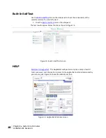
Page 18: ...test results appear below the link as shown in Figure 14 Figure 14 Built In Self Test screen HELP Welcome to HughesNet The HughesNet web portal contains a variety of useful tools resources and information Access to the HughesNet portal is determined by your service plan Figure 15 shows the Welcome screen Figure 15 HughesNet Welcome screen 18 Chapter 2 System Control Center 1039650 0001 Revision A ...

Page 19: ...Chapter 2 System Control Center 1039650 0001 Revision A 19 ...

Page 20: ......

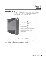
Page 21: ...ating status The front panel LEDs are blue when lit Figure 16 Front panel LEDS Table 2 explains what the modem status is when the LEDs are on off or blinking On means the LED is continuously lit Blinking means the LED is usually on but intermittently turns off briefly Flashing means the LED alternates between on and off for periods of sec to 1 sec Chapter 3 LEDS 1039650 0001 Revision A 21 ...

Page 22: ...eventing transmission Receive ON OK Receive path is operational Blinking Receiving data Off Condition preventing receipt of data System ON Connection established with the NOC Off Condition preventing full operation Power ON Red color Power is on and the modem is functioning normally Indicates overheating Flashing Operating with fallback bin backup version of software Off No power Bold type indicat...

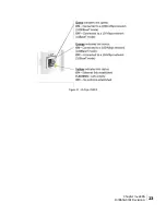
Page 23: ...Figure 17 LAN port LEDS Chapter 3 LEDS 1039650 0001 Revision A 23 ...

Page 24: ......

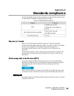
Page 25: ...cations company cause to request the user to disconnect the equipment Users should not attempt to make electrical ground connections themselves but should contact the appropriate electrical inspection authority or electrician as appropriate Electromagnetic interference EMI This product conforms to EMI standards of the U S FCC and Canadian CSA as detailed in the following sections The installation ...

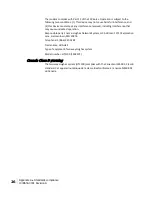
Page 26: ...on Responsible party s name Hughes Network System LLC Address 11717 Exploration Lane Germantown MD 20876 Telephone 1 866 347 3292 Trade name HUGHES Type of equipment Two way Hughes system Model number HT1100 1502573 Canada Class B warning The two way Hughes system HT1100 complies with the Canadian ICES 003 Class B standard Cet appareil numérique de la classe B est conforme á la norme NMB 003 du Ca...

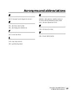
Page 27: ...gnetic interference F FAP Fair Access Policy L LAN Local area network N NetBEUI Extended User Interface network transfer protocol Networking requirements NOC Network Operations Center S SAN Site account number V VAR Valued added reseller LED Light Emitting Diode Acronyms and abbreviations 1039650 0001 Revision A 27 ...

Page 28: ......
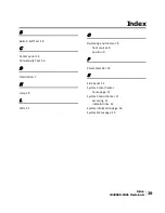
Page 29: ... 7 H Help 18 L LEDs 21 O Operating environment 8 heat sources 8 position 9 P Parameters bar 14 S Side panel 14 System Contol Center home page 11 System Control Center 11 accessing 11 indicator links 12 System Information page 16 System Status page 15 Index 1039650 0001 Revision A 29 ...

Reviews: