


38
OPERATE
VOL.
PAGE
BACK
PRESET
ZOOM
FOCUS
COMPUTER VIDEO
QUICK
ALIGN.
AV
MUTING
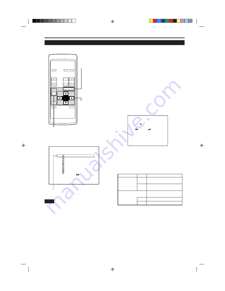
W
T
MENU/ENTER
MENU/ENTER
button
Cursor buttons
PAGE BACK button
Operating the Main Menu (Cont.)
Adjusting the Pixel Clock
Submenu item (PIXEL CLOCK)
The pixel clock should be adjusted mainly for computer-related inputs.
(Normally, it does not need to be adjusted for video inputs.) If a wide
stripe appears on the screen, adjust the lateral size of video image
and the display area (tracking adjustment) so the stripe disappears.
Also, if text on the video screen appears flickering or dim, make
adjustment so it becomes clear (phase adjustment).
1
Press the MENU/ENTER button.
• The main menu appears on the screen.
2
Select “PIXEL CLOCK” with the cursor
button
5
or
∞
.
• The selected item (displayed in text) is shown in magenta color
on the screen.
3
Press the MENU/ENTER button.
• The submenu items of the PIXEL CLOCK menu appear on the
screen.
(PIXEL CLOCK menu)
4
Adjust “TRACKING” and “PHASE” with
the cursor buttons.
• Adjust the tracking and phase of the video screen being
projected. To adjust the phase, first check for correct tracking
adjustment.
* To reset to the factory-set adjustment values, press the remote
control’s PRESET button.
Tracking and phase are reset to the factory-set adjustment values.
To return to the main menu, press the PAGE
BACK button. To finish the main menu, press
PAGE BACK again.
• To finish the menu display from the submenu display (PIXEL
CLOCK menu), press PAGE BACK twice.
The screen shrinks laterally
(right-to-left). (–255
←
0
←
+255)
The screen extends laterally
(right-to-left). (–255
→
0
→
+255)
Set to a position where text
appears clear.
(–127
→
0
→
+127)
(–127
←
0
←
+127)
Adjustment item Button
Adjustment content
TRACKING
PHASE
2
3
5
∞
■
Remote control unit
■
Main menu
Notes
• The selected item is shown in magenta color. Items shown
in gray color cannot be operated or set in the current mode.
• A dim screen could be caused by insufficient adjustment of
brightness and contrast. Before adjusting phase, make sure
that brightness and contrast are correctly adjusted.
P I X E L C L O C K
T R A C K I N G P H A S E
0 0
C H : 1
C O M P 1 S X G A 2
P I X E L C L O C K
P O S I T I O N
P I C T U R E
S O U N D
O P T I O N S
S O U R C E
C H A N N E L
U S E R S O U R C E S E T U P
D I S P L A Y S I Z E
D E C O D E R A U T O ( N T S C ( 4 8 0 i ) )
L A N G U A G E E N G L I S H
G2000 p.35-59
99.11.20, 3:29 AM
38


