background image

14  

A

ssembly

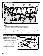
Install the Spoiler:

Install the Exhaust Pipes:

STEP 1:

•  Position Spoiler 

A

 with Stabilizers 

B

 to the rear as shown.

•  Line up Spoiler Mounting Holes and install 6 Screws 

C

 loosely.

STEP 2:

•  Insert bottom of each Stabilizer 

B

 until they SNAP into position in Mounting Holes 

D

.

•  Tighten the 6 Screws 

C

 evenly and securely.  Do not over-tighten.

A

B

D

C

A

B

NOTE: 

Exaust Pipes are marked 

with an 

L

 and 

R

 for each side.

•  Install the left Exhaust Pipe 

A


on the left side by lining up 

the tabs on the body 

B

 and 

snapping firmly into place.

•  Repeat for opposite side.

Summary of Contents for m0409

Page 1: ...nements le service à la Clientèle Copyright Huffy Corporation 2017 Owner s Manual for Battery Ride On Please read and fully understand this manual before operation Save this manual for future reference This manual contains important safety assembly operation and maintenance information H LMC Rideon EN 060717 m0409 BC Date Code Label Here EN ...

Page 2: ...ranty Limited Warranty 22 Contact Information Back Cover WARNING CHOKING HAZARD Small parts adult assembly required To reduce the risk of injury adult supervision is required Never use in roadways near motor vehicles on or near steep inclines or steps swimming pools or other bodies of water always wear shoes and never allow more than one rider The user must be 3 years and weigh no more than 65 lbs...

Page 3: ...ools sloped surfaces hills wet areas flammable vapors in alleys at night or in the dark could result in an accident Do not use the vehicle in unsafe conditions such as snow rain loose dirt mud sand or fine gravel This may result in unexpected action such as tip over and skidding Models with no brakes Motor friction will gradually stop the unit Do not use the vehicle in an unsafe manner Examples in...

Page 4: ...ons However there is no guarantee that interference will not occur in a particular installation If this equipment does cause harmful interference to radio or television reception which can be determined by turning the equipment off and on the user is encouraged to try to correct the interference by one or more of the following measures Reorient or relocate the receiving antenna Increase the separa...

Page 5: ...fire or electric shock Always keep all liquids away from the battery and keep the battery dry Contact or exposure to battery leakage lead acid may cause serious injury If contact or exposure occurs immediately call your physician If the chemical is on the skin or in the eyes flush with cool water for 15 minutes If the chemical was swallowed immediately give the person water or milk Do not give wat...

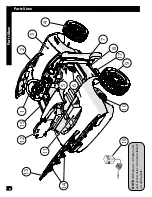
Page 6: ...6 Parts View Parts View 13 12 15 11 1 2 4 3 7 5 6 8 17 9 10 16 14 NOTE All features components and accessories are not included on all models ...

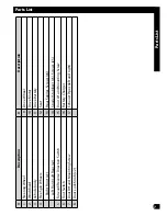
Page 7: ... 11 Drive Battery 4 Free Spin Wheels 12 Seat Right Front x1 13 Rear Spoiler Screws x6 Left Front Left Rear x2 14 Spoiler Stabilizer x5 Screws x5 5 Forward Reverse Direction Switch 15 Door LH and Mounting Screw 6 Foot Switch 16 Battery Charger 7 Door RH and Mounting Screw 17 Exhaust Pipes left and right 8 Door Lock Knob x2 ...

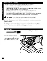
Page 8: ...ll models Use the Index page to locate specific sections of this manual Please read through this entire manual before beginning assembly or maintenance If you are not confident with assembling this unit contact customer service WARNING Keep small parts away from children during assembly NOTE All of the directions right left front rear etc in this manual are as seen by the rider while seated Do not...

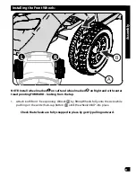
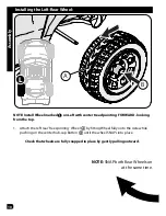
Page 9: ...ight and with center tread pointing FORWARD looking from the top 1 Attach both front free spinning Wheels Aby fitting Wheels fully onto the Axle while pushing on the center hub cap Button Buntil the wheels SNAP into place Check that wheels are fully snapped in place by gently pulling outward A B L R ...

Page 10: ...ORWARD looking from the top 1 Attach the left rear free spinning Wheel Aby fitting Wheel fully onto the Axle while pushing on the center hub cap Button Buntil the wheel SNAPs into place Check that wheels are fully snapped in place by gently pulling outward A B L NOTE SNAP both Rear Wheels on at the same time ...

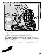
Page 11: ...heel while installing the Right Wheel 1 Attach rear Drive Wheel Aby fitting Wheel fully onto the Axle and making sure Notches Balign with Motor C then pushing on the center hub cap Button Duntil the wheel SNAPS into place Check that Drive Wheel is fully snapped in place by gently pulling outward C B A D ...

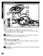
Page 12: ...N Put the connected plugs down into the car body hole so that Steering wheel attaches easily and wires are not pinched or bound up STEP 2 While pulling UP on Steering Rod C Install the Steering Wheel Donto the Steering Rod end Eso that all Mount Holes line up Install the Screw Gand Locknut Fas shown Tighten Screw Gsecurely CAUTION Ensure Steering Wheel turns freely from side to side without bindin...

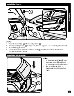
Page 13: ...and securely 2 Test by pulling up slightly Windshield should not pull out easily STEPS 1 Position Door Hinge Ainto car body Recess B 2 Install mounting Screw Csecurely Do not over tighten This can damage the mount 3 Repeat for opposite side 4 Ensure doors close correctly and Door Locks Dhold the doors shut when turned towards the REAR as shown A B ...

Page 14: ...s Cloosely STEP 2 Insert bottom of each Stabilizer Buntil they SNAP into position in Mounting Holes D Tighten the 6 Screws Cevenly and securely Do not over tighten A B D C A B NOTE Exaust Pipes are marked with an L and R for each side Install the left Exhaust Pipe A on the left side by lining up the tabs on the body Band snapping firmly into place Repeat for opposite side ...

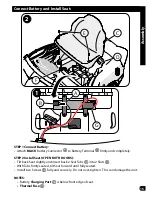
Page 15: ...ly STEP 2 Install Seat OPEN BOTH DOORS Tilt back Seat slightly and insert back 2 Seat Tabs Cinto 2 Slots D With Tabs firmly seated tilt Seat forward until fully seated Install two Screws Efully and securely Do not over tighten This can damage the unit NOTES Battery Charging Port Fis below front edge of seat Thermal Fuse G D A G B F C E 1 2 ...

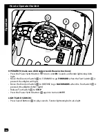
Page 16: ...e Direction Switch Bto FORWARD to go FORWARD when the Foot Switch Cis pressed Headlights will light Move the Direction Switch Bto REVERSE to go BACKWARDS when the Foot Switch Cis pressed Headlights do NOT light Release Foot Switch Cto STOP Press the Power Switch button Aagain to turn unit OFF LIGHTS AND SOUNDS Press Sound Buttons Dto play sounds Fender lightening bolts also light D A B C ...

Page 17: ...ctions Parts that are not tight enough can be lost or operate poorly Over tight ened parts can be damaged Make sure any replacement fasteners are the correct size and type Check the tightness of the wheels Note If the drive wheel is not tight it will not engage the gears and the vehicle will not run Ensure the battery bracket is securely in place before use Store the vehicle indoors Keep it away f...

Page 18: ...to storage Wash cloth separate from other clothes BATTERY DISPOSAL The sealed lead acid battery must be re cycled or disposed of in an environmentally sound manner Do not dispose of battery in a fire The bat tery may explode or leak acid Do not dispose of the battery in house hold trash The incineration land filling or mixing of sealed lead acid batteries with household trash is prohibited by law ...

Page 19: ... is depleted recharge for 8 to 12 hours never longer than 20 hours Do not short circuit the battery Do NOT connect red and black wires together or connect positive and negative terminals on the battery together When battery is fully charged un plug charger from the wall outlet and disconnect from charger port The drive battery should be charged when depleted or if not used regularly once a month F...

Page 20: ...fully charged Replace battery see Battery Replace ment and Disposal Vehicle runs sluggishly Battery low on power Recharge battery see Battery Replace ment and Disposal Battery is old and cannot be fully charged Replace battery see Battery Replace ment and Disposal Vehicle is overloaded Reduce weight on vehicle see user requirements and Safety Warnings Vehicle is being used in harsh conditions Avoi...

Page 21: ...icking noises coming from motor or gear box Motor or gears are dam aged Call Customer Service Drive Wheel is partially engaged Check drive wheel to motor engage ment Battery will not recharge Battery connector or adapter connector is loose Check that the battery connectors are firmly plugged into each other Charger not plugged in Charger is not working Check that the battery charger is plugged int...

Page 22: ...by improper assembly maintenance adjustment storage or use of the product This Limited Warranty will be void if the product is ever Used in any competitive sport Used for stunt riding jumping aerobatics or similar activity Modified in any way Modified with the addition of a motor Ridden by more than one person at a time Rented sold or given away Used in a manner contrary to the instructions and wa...

Page 23: ...NOTES ...
Page 24: ...om contact To Order Parts CANADA only go to http www huffybikes com parts OU appelez le 1 800 872 2453 CANADA only Pour communiquer par courriel huffycanada huffy com MÉXICO ANTES DE DEVOLVER EL PRODUCTO A LA TIENDA COMUNÍQUESE CON SERVICIO AL CLIENTE DE HUFFY NOS COMPLACE AYUDARLO CON CUALQUIER PARTE O PROBLEMA DE ENSAMBLADO QUE PUDIERA TENER Para obtener Servicio al cliente rápido visite http www...

Reviews: