Hubble AM-10 Manual Download Page 12

10

CURRENT LIMITING FUNCTION

The BMS has a advanced current limiting function built in. The charge current limiter is designed 

to activate if charging current has reached the maximum battery design charge limit. This ensures 

the battery does not disconnect from the circuit and the current limiter takes over and reduces the 

charge to 20Amps per battery.

The default start-up condition of the charging current limit is to start when the charging current 

is greater than 100A. After entering the current limit, the test will be performed again every 10 

minutes. When the current is less than the current limit start value, the current limit function will be 

turned off. When the current is bigger than the current limit start value, then the current limiting 

mode with stay enabled.

COMMUNICATION DESCRIPTION 

1.  The RS232 port is only for use with Hubble specific periphirals or technicians or at a service 

centre to interface with the BMS. Attempting to use this port for anything else or 3rd party 

products can cause damage. 

2.  The CAN Port is specifically to be used to any interfacing 3rd party equipment like inverters 

etc. This port is dedicated to inverters and other CAN bus ports for communication to get 

battery information. 

3.  The RS485 communication port can be interfaced with 3rd party inverters that does not 

have a CAN port and is supported by Hubble. 

4.  The Battery link ports are only for connecting more batteries of the same model to increase 

capacity and to enable multiple battery communications.


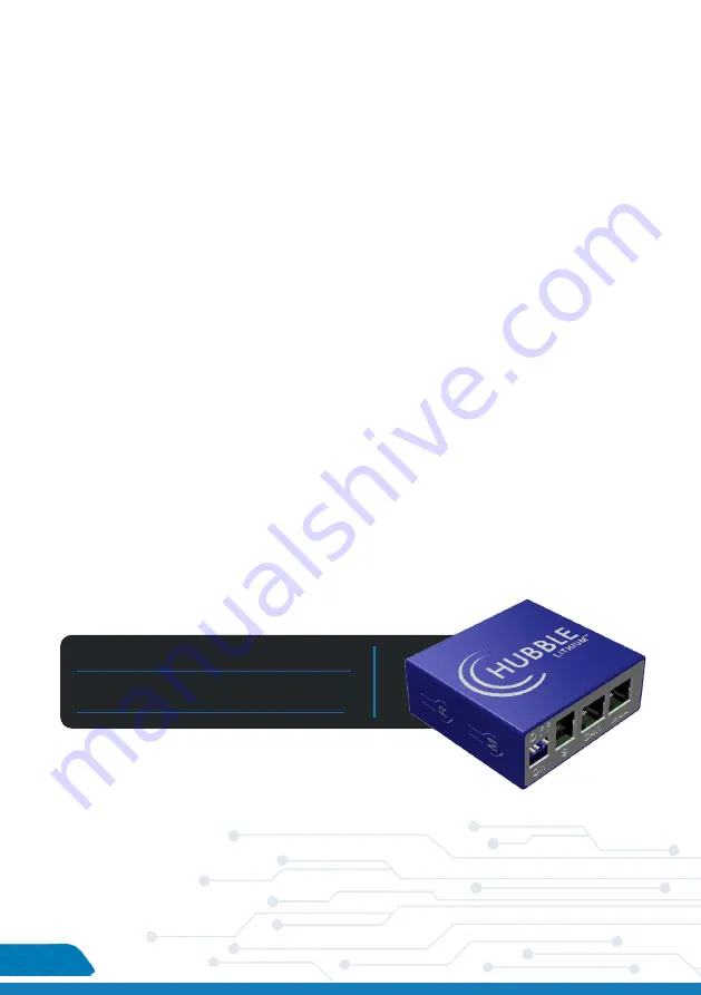
OPTIONAL CLOUDLINK DEVICE

The Hubble Cloudlink is an optional add-on to the Hubble X and AM range of products. As long 

as the device is connected to Wi-Fi it will cloud, all battery and inverter data to our cloud-server, 

enabling users to remotely monitor their power system.

Learn more about the Hubble Cloudlink here:  

https://www.hubblelithium.co.za/hubble-cloudlink.html 


Access the latest Coudlink Setup Guide here: 

https://www.hubblelithium.co.za/cloudlink-setup.html

Summary of Contents for AM-10

Page 1: ...teps to ensure correct inverter compatibility Please visit www hubblelithium co za for the latest version of this manual V 1 0 WARNING Working with high voltage systems is dangerous Do not attempt to modify your inverter and battery setup unless you are certain you understand the risk Speak to a qualified electrician if you are unsure ...

Page 2: ...EX product description 1 product Specifications 2 PARALLEL CONNECTION OF BATTERIES 3 installation notes 4 interface definiton 7 interface FUNCTIONS 10 PARALLEL FUNCTIONS 11 warnings 12 COMPLETING SETUP 13 ...

Page 3: ...phate battery application technology and BMS control technology TECHNICAL SPECIFICATIONS Model AM 10 Battery Type LiFePO4 LFP Norminal Voltage V 51 2V Norminal Energy KWH 10KWH Design Capacity 200AH Design Years 15 Years PRODUCT SIZE Size 673 618 193mm Weight 89kg TECHNICAL PARAMETER Cycle Life 6000 80 DOD Operating Voltage Range 40V 58 4V Charging Voltage DC 58 4V Charge Discharge Current A Same ...

Page 4: ...INTERFACE SIZE 2 1 POWER SWITCH 2 DRY CONTACT 3 RESET 4 ADDRESS 5 RS485 6 CAN 7 RS232 8 BATTERY LINK 9 BATTERY 10 BATTERY ...

Page 5: ...PARALLEL CONNECTION OF BATTERIES 3 SOLUTION DIAGRAM Connect the positive pole and positive pole in parallel and the negative pole and negative pole in parallel as shown in the figure below INVERTER ...

Page 6: ...rom wall and drill the holes 2 As shown in the figure below fix the attached six expansion bolts in the opening of the mounting structure and tighten the nuts on the bolts 3 Lift up the AM 10 battery carefully and hook it into position securely onto the wall mount bracket 4 WALL POSITION PUNCHING 6PCS BOX PENDANT OPENING POSITION FIXED PENDANT AFTER COMPLETION AS SHOWN IN THE FIGURE ...

Page 7: ...hting If there is no charging the LED light is in standby state Temperature Over current Protection OFF Lighting OFF OFF OFF OFF Stop charging DISCHARGE Normal Flash 3 OFF According to the electricity instruction Alarm Flash 3 Flash 3 Undervoltage protection OFF OFF OFF OFF OFF OFF Stop discharge Temperature Overcurrent Short circuit Reverse connection Failure protection OFF Lighting OFF OFF OFF O...

Page 8: ...OFF OFF OFF 3 OFF ON OFF OFF 4 ON ON OFF OFF 5 OFF OFF ON OFF 6 ON OFF ON OFF 7 OFF ON ON OFF 8 ON ON ON OFF 9 OFF OFF OFF ON 10 ON OFF OFF ON 11 OFF ON OFF ON 12 ON ON OFF ON 13 OFF OFF ON ON 14 ON OFF ON ON 15 OFF ON ON ON 16 ON ON ON ON table 4 dual switch position ...

Page 9: ...uter receiving data foot PIN 4 RX protection board receives data computer sends data PIN 5 Ground signal ground PIN 6 NC empty INTERFACE DEFINED DECLARATION DEFINED DECLARATION X1 Communication port definition RJ45 CAN pin layout PIN 1 CANL RJ45 RS485 pin layout PIN 1 RS485 B1 PIN 2 CGND PIN 2 RS485 A1 PIN 3 NC empty PIN 3 RS485 GND PIN 4 CANH PIN 4 RS485 B1 PIN 5 CANL PIN 5 RS485 A1 PIN 6 NC empt...

Page 10: ...IN 5 NC empty PIN 6 RS485 GND PIN 6 RS485 GND PIN 7 RS485 A2 PIN 7 RS485 A2 PIN 8 RS485 B2 PIN 8 RS485 B2 This BMS can provide one channel of dry contact signal all dry contact signals are passive switch es regardless of polarity KRY 1 2P terminal BMS STATE DESCRIPTION REMARK Normal Operation 1 2 pin is disconnected BMS Alarm 1 2 pin is connected Output when SOC alarm under voltage and over voltag...

Page 11: ...en the following conditions are met the system will enter the sleep mode 1 The over discharge protection of the BMS has not been released for 5 minutes 2 The duration of the standby state has reached 24 hours no communication no charge and discharge no charger connected DESCRIPTION OF WAKE UP FUNCTION Please note that the battery enters sleep mode due to single or overall over discharge and cannot...

Page 12: ...or at a service centre to interface with the BMS Attempting to use this port for anything else or 3rd party products can cause damage 2 The CAN Port is specifically to be used to any interfacing 3rd party equipment like inverters etc This port is dedicated to inverters and other CAN bus ports for communication to get battery information 3 The RS485 communication port can be interfaced with 3rd par...

Page 13: ...data of each battery pack in this cascaded system When the battery packs are cascaded only the main battery pack can communicate with the host computer upload the data status and information of all battery packs in the cascaded system integrate monitoring and management and realize remote monitoring RS485 PARALLEL WIRING DIAGRAM When performing multi machine parallel communication operation it is ...

Page 14: ... Never use a modified or damaged charger STORAGE Store the battery in a cool dry and well ventilated area DISPOSAL Regulations vary for different countries Dispose of in accordance with local regulations Battery Operation Instruction CHARGING Charging current Do not surpass the specified charging current Charging voltage Do not surpass the specified charging voltage Ensure correct DC polarity befo...

Page 15: ...provide you with timely assistance 1 Inverter make model 2 Model number of connected batteries 3 Are your batteries in Series or Parallel 4 A brief description of your system and any issues you may be having 5 If possible images of your power system 6 Contact Details if we should need to contact you CONGRATULATIONS Information published on this manual is correct as of the date published on this ma...

Reviews: