background image

cement lining includes an inspection to ensure that the lining is applied to the 
correct thickness, covers all appropriate surfaces, and is free from defects or 
cracks greater than 3 mm (1/8”) in width.  Any deficiencies are repaired at the 
factory prior to shipment.   However, it is characteristic to find hairline cracks 
in the cement lining prior to initial installation. After the vessel is first filled, the 
water will work its way into these cracks and begin the corrosion process. At 
the same time the cement lining undergoes a “wet curing” process whereby the 
cement absorbs water and expands. The water that is absorbed into the lining 
becomes trapped between the cement lining and the steel tank and once the 
cement is fully absorbed with water, the water in contact with the steel tank 
becomes deoxygenated which serves to protect the steel vessel. In addition, the 
cement leaches minerals and various impurities from the water which fills and 
“heals” the cracks. This “healing” together with the “wet curing” and expansion 
of the cement prevents any ongoing corrosion. In the unlikely event a crack 
greater than 3 mm (1/8”) develops, the cement lining can be easily repaired in 
the field. For repair procedures please contact Hubbell 
a.


Shut down unit as described in Section II. 

b.


Close valve on hot water outlet piping. 

c.


Open valve on drain piping. 

d.


Cold water inlet line pressure will be strong enough to flush sediment from 
the bottom of the tank out through the drain. Let water run for 3-4 minutes. 

e.


Clean strainer filter, see below. 

f.


Close drain valve. 

g.


Open hot water valve. 

h.


Re-start unit as described in Section II. 

17.


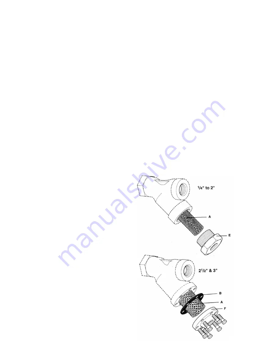
Clean strainer filter. Perform 
annually or more often , if 
required. 
a.


Remove blowoff bushing 
(E) or cap (F), as required. 

b.


Remove gasket (B), if 
required. 

c.


Remove, clean, and re-
install screen (A). 

d.


Replace gasket (B). 

e.


Re-install blowoff bushing 
(E) or cap (F), as required. 


15

Summary of Contents for ST

Page 1: ...OPERATING AND MAINTENANCE MANUAL FOR STEAM FIRED WATER HEATER ELECTRIC HEATER COMPANY BASE MODEL ST and STH ...

Page 2: ...l with the high voltage power supply turned on Under certain circumstances dangerous potentials may exist even when the power supply is off To avoid casualties always turn the power supply safety switch to off turn the charge or ground the circuit before performing any maintenance or adjustment procedure 5 Generalized instructions and procedures cannot anticipate all situations For this reason onl...

Page 3: ... I GENERAL DESCRIPTION AND CONSTRUCTION 7 II INSTALLATION AND OPERATION 9 III SCHEDULED MAINTENANCE AND OPERATION 12 IV ADJUSTMENT AND TEMPERATURE REGULATORS 18 V TROUBLESHOOTING 20 VI MISCELANEOUS CHARTS AND FORMULAS 22 3 ...

Page 4: ...4 ...

Page 5: ...NOMENCLATURE FOR PARTS 5 ...

Page 6: ...NOMENCLATURE FOR ACCESSORY PARTS 6 ...

Page 7: ...ry tested to ensure long lasting protection of the steel vessel 3 Flame Spray Copper Molten copper is sprayed on the interior surfaces to a thickness of 5 6 mils The copper bonds to the steel and an additional overcoat of Phenolic lining is applied on the copper to seal all pores 4 Galvanizing The steel pressure vessel is pickled and hot dipped in molten zinc to create a barrier which internally a...

Page 8: ...ons A cast iron Y strainer with 20 mesh screen protects the steam controls and coil from dirt and debris in the steam supply Traps Two traps should be utilized in the immediate steam piping system of the water heater The first trap in the system is a drip trap that is designed to collect condensate from the main steam line before entering the steam regulator Additionally a main condensate trap sho...

Page 9: ...hould the temperature in the tank reach the high limit set point This option requires 120 volt 5 amp electrical service Double Solenoid Safety System A double solenoid safety system dumps over heated water in the storage tank to drain in addition to closing the steam supply to the control valve This option requires 120 volt 5 amp electrical service Anticipator Control System The anticipator contro...

Page 10: ...l to permit proper drainage PIPING INSTALLATION NOTE The most effective means for preventing deterioration from accelerated corrosion due to galvanic and stray current is the installation of dielectric fittings unions The installation of these fittings is the responsibility of the installing contractor 1 All integral components have been properly sized to meet design conditions Piping to the unit ...

Page 11: ...e of power is required for the valve See enclosed operation and maintenance manual for specific valves 2 If the unit is furnished with an air or electric control valve see enclosed drawings for required connections See enclosed operation and maintenance manuals for specific valves Torque screws per torque chart included in Section VI 11 ...

Page 12: ... vented to eliminate trapped air Monitor the tank temperature until the desired temperature is reached If the temperature regulator shuts off before the desired temperature is reached or if over shoot occurs adjustment of the temperature regulator will be required Refer to enclosed O M manuals for your specific control valve 4 After control valve adjustments have been made and the desired temperat...

Page 13: ... the equipment and the unit is drained 3 In cleaning a tube bundle tubes should not be hammered on If it is necessary to use scrapers care should be taken to insure that the tubes are not damaged 4 Before it is necessary to apply mechanical means for cleaning try to clean the unit using the following methods a Circulate hot fresh water at a reasonable velocity b Try spraying with water hose c Cons...

Page 14: ...ow pressure to build up letting the water pressure seal the gasket Some leakage may occur at this point but as the gasket seats leaking will gradually stop After leaking has stopped turn the nut approximately 1 revolution At this point there may be some miner seepage wait a few minutes to see if this seepage stops If seepage continues drain the tank inspect the manhole ring and cover for any damag...

Page 15: ...steel vessel In addition the cement leaches minerals and various impurities from the water which fills and heals the cracks This healing together with the wet curing and expansion of the cement prevents any ongoing corrosion In the unlikely event a crack greater than 3 mm 1 8 develops the cement lining can be easily repaired in the field For repair procedures please contact Hubbell a Shut down uni...

Page 16: ...16 ...

Page 17: ...SINGLE SAFETY SOLENOID SYSTEM if installed 17 ...

Page 18: ... required on this job 2 Whenever possible Hubbell uses fail safe regulators This means that if the controlling medium such as air or water is lost the valve will close under it s own spring tension 3 ADJUSTMENT OF 2 WAY AIR OR WATER OPERATED VALVES a Release all air pressure from the diaphragm b Apply steam pressure to the valve c If at this point there is pressure on the downstream side of the va...

Page 19: ...oupling A d Lift lower stem B and hold against upper valve seat e Turn adjustment screw C until there is approximately a 1 16 inch gap between the two stem halves f Apply air pressure to valve diaphragm so that stem halves are aligned and re connect stem halves g If valve will not open with air on the diaphragm spring tension should be decreased h Adjustment is essentially the same as if spring te...

Page 20: ...l turn stop and allow valve to shut off 7 Repeat this cycle until unit is up to the desired temperature SECTION V TROUBLESHOOTING See separate component O M for additional details Symptom Probable Cause Corrective Action Remedy Gradual loss of heating capacity Tubes are fouled Clean tubes per Section III annual scheduled maintenance Excess silt in bottom of tank Drain and flush tank per Section II...

Page 21: ...hragm on temperature control valve Repair or replace per separate O M Defective steam trap Repair or replace per separate O M Blockage in condensate line Clean blockage from condensate line Loss of air pressure on temperature regulator Check air pressure to temperature regulator Verify that it is within limits Adjust as necessary Excessive vibration High rate of flow beyond design conditions Consu...

Page 22: ...1 4 20 75 2 61 5 68 8 45 6 78 8 85 3 1 4 28 94 0 77 0 87 0 57 0 99 0 106 0 5 16 18 132 107 123 80 138 149 5 16 24 142 116 131 86 147 160 3 8 16 236 192 219 143 247 266 3 8 24 259 212 240 157 271 294 7 16 14 376 317 349 228 393 427 7 16 20 400 327 371 242 418 451 1 2 13 517 422 480 313 542 584 1 2 20 541 443 502 328 565 613 9 16 12 682 558 632 413 713 774 9 16 18 752 615 697 456 787 855 5 8 11 1110...

Page 23: ...NOTES 23 ...

Page 24: ...P O BOX 288 STRATFORD CT 06615 0288 PHONE 203 378 2659 FAX 203 378 3593 INTERNET http www hubbellheaters com 24 ...

Reviews: