6
A.
Handle Sub-Assembly
(E309-
0819 & Related Parts) All handles
marked with Part No. "19671", no
revision letter or "19671-F" should
be replaced with E309-0819 because
of possible part interchangeability
problems.
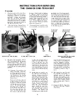
(1) Examine "stop surfaces for
impact damages caused by
such improper practices as al-
lowing handle to self-ratchet,
and "slamming" the handle
unnecessarily during use.
Refer to fig. 1.
Excessive battering and sub-
sequent eroding, of the "stop"
surfaces, on both the handle
and housing, can cause shear-
ing of the housing spring
retaining screw (56163). As
the surfaces are eroded away,
the clearance between the
tip of the unloader plate and
the screw is reduced enough
to allow the unloader plate to
strike the screw. Refer to Fig.
2. Screw shearing, can also
occur if the hoist is allowed to
"self-ratchet", the momentum
of the unloader plate can cause
it to exceed its normal amount
of travel and strike the spring
screw.
(2) Handle damage caused by ap-
ply "cheaters" (extensions) to
increase leverage and other
improper practices is quite com-
mon on hoists returned to the
factory for repair. Such hoists
may have been dangerously
overloaded as a result of such
usage. Any hoist exhibiting
evidence of this type of treat-
ment, and even undamaged
hoists, should be most care-
fully examined—particularly
the principle load carrying
members. The holding and
working dog assemblies (pawls)
must be checked and replaced
if they show any evidence of
creasing, chipping, or cracking.
The ratchet teeth on the forged
heat treated shaft (P309-0791)
must be checked for missing or
damaged teeth, and replaced
if necessary. Refer to Fig. 3
& 10.
(3) The handle dog (pawl) should
be examined for damage as
outlined in part (2), and in
addition, the dog pin (19315)
should be examined for bending
or wear in the area that the pin
contacts the camming surface
of the unloader plate. Refer to
Fig. 3 & 4.
(4) Stop bolt 19673. Check for
bending or breakage. Replace
if necessary.
2. After load testing, thoroughly ex-
amine the exterior hoist parts for
damage. Check hooks for bending
or "opening" caused by incorrectly
loading the hook tip, or jamming the
housing out of line during loading—
replace if bent or opened. For swivel
hook models, inspect bearings for
wear. On all models check all cast-
ings for wear, taking corrective
measures if necessary.
3. Disassemble hoist carefully, refer
to disassembly instructions and
exploded view of hoist components.
Wash all parts in a suitable cleaner,
remove all oxides and foreign mate-
rial. Examine mechanism for dam-
aged or excessively worn parts, refer
to the accompanying photographs
for typical examples. Replace all
parts showing evidence of excessive
wear or indications of damages.
Particular attention should be given
to the following areas:
Procedure
1. Check operation of the hoist thor-
oughly by lifting and lowering a
minimum of 500 lb. (rated load
preferred). Lifting and lowering
operations should be checked by
operating the hoist in the two posi-
tions of operation, that is, using both
downward and upward strokes to
lift and lower the test load.
INSTRUCTIONS FOR SERVICING
THE CHANCE ONE-TON HOIST
FIG. 2
CUT AWAY VIEW OF "STOP" AREA
Pin Wear At Point
of Contact With
Unloader Plate
Inspect For Pin Wear
At Point of Contact
With Unloader Plate
FIG. 3
DAMAGED PAWLS
FIG. 4
CUT AWAY SHOWING PAWL PIN & UNLOAD-
ER PLATE RELATIONSHIP
FIG. 1
PRINCIPLE "STOP" AREA OF HANDLE
Housing
"Stop"
Screw
56163
Severe
Crease
Note
Crushing
Handle "Stop"
Tip of Unloader
Plate
Impact Damage


