INSTALLATION, OPERATION AND MAINTENANCE
MANUAL FOR
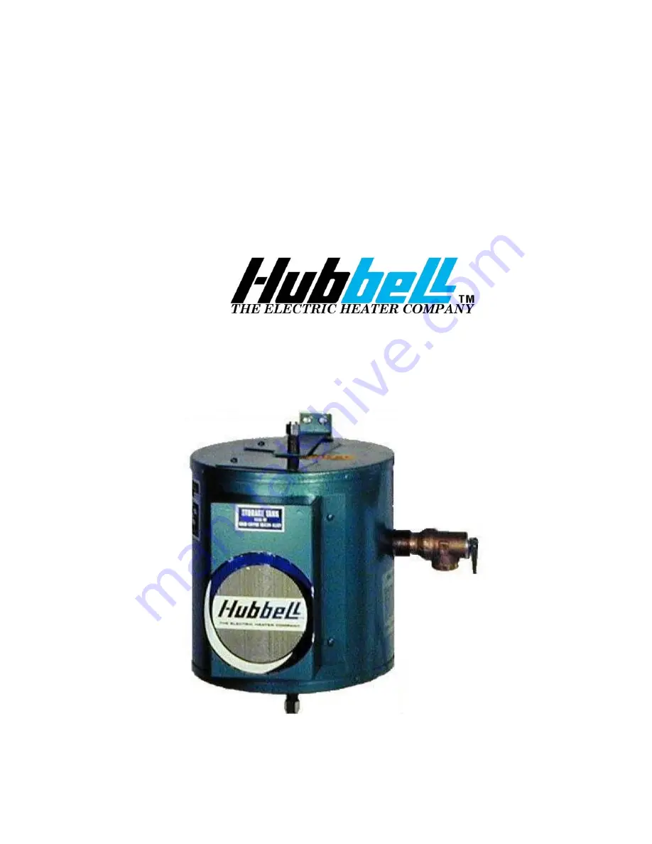
COMMERCIAL ELECTRIC WATER HEATER
BASE MODEL “ CE110 ”
2009 Edition
Page 1: ...INSTALLATION OPERATION AND MAINTENANCE MANUAL FOR COMMERCIAL ELECTRIC WATER HEATER BASE MODEL CE110 2009 Edition...
Page 2: ...93 INTERNET http www hubbellheaters com IMPORTANT Always reference the full model number and serial number when calling the factory The following information should be noted at time of installation an...
Page 3: ...d casualties always turn the power supply safety switch to off turn the charge or ground the circuit before performing any maintenance or adjustment procedure 7 This appliance is designed to store wat...
Page 4: ...OF CONTENTS SECTION TITLE PAGE I GENERAL INFORMATION 6 II INSTALLATION GUIDELINES 8 III SCHEDULED MAINTENANCE AND OPERATION 14 IV TROUBLESHOOTING 16 V SERVICING AND REPLACEMENT OF PARTS 17 VI WARRANTY...
Page 5: ...s heavy gauge steel finished with high gloss enamel Insulation consists of high density fiberglass blankets Temperature Pressure Safety Relief Valve Hot Water Outlet Cold water inlet not shown on bott...
Page 6: ...overflow line should be utilized from the relief valve outlet to a floor drain See drawing for locations and sizes HEATING ELEMENT The water heater is supplied with either a 1000 watt or a 450 watt e...
Page 7: ...r Relief Valves and Automatic Gas Shutoff for Hot Water Supply Systems ANSI Z21 22 1971 A relief valve is designed to discharge excessively hot water THE CUSTOMER IS RESPONSIBLE TO PROTECT PROPERTY AN...
Page 8: ...alve and tank or in the drain line FILLING THE HEATER 1 Completely close the drain valve 2 Open the highest hot water faucet to allow all air to escape from piping 3 Open the valve to the cold water i...
Page 9: ...ld water line f Hot water line connected to hot water outlet on tank g Temperature and pressure relief valve installed h Relief valve overflow line installed i Water heater filled with water j Power l...
Page 10: ...ION WITHOUT TEMPERING VALVE Piping to Hot Water Piping from Cold Water Air Gap Drain Valve Relief Valve Discharge Pipe Temperature Pressure Relief Valve Support Bracket bottom bracket not shown Floor...
Page 11: ...TH TEMPERING VALVE Piping to Hot Water Tempering Valve Support Bracket bottom bracket not shown Air Gap Floor Drain Relief Valve Discharge Pipe Temperature Pressure Relief Valve Piping from Cold Water...
Page 12: ...ly clicks off draw water from heater c Measure the maximum temperature with an accurate thermometer d If the temperature is above the safe limits for your circumstances call a service man to adjust or...
Page 13: ...mit switch tripped Reset high limit switch Loose wires Tighten wires Torque screws per torque chart included in Section VI Heating element inoperable Check heating element operation by clamping an Amp...
Page 14: ...screws 5 Replace control and install new high limit switch by performing above steps in reverse order refer to wiring diagram in Section II Torque screws per chart in back HEATING ELEMENT 1 Disconnect...
Page 15: ...all access cover 13 Fill tank and check around element for any leaks THERMOSTAT 1 Disconnect power from unit 2 Remove access cover and locate thermostat 3 Disconnect the two 2 control wires Wires Capi...
Page 16: ...e to relieve pressure in tank 4 Disconnect overflow piping 5 Unscrew relief valve remove assembly and replace with new one 6 Connect overflow piping 7 Turn on incoming water supply and check for leaks...
Page 17: ...the Company TANK REPLACEMENT POLICY TEN YEARS This section outlines the ten year limited replacement policy for tanks that fail due to the corrosive effects of water Duration Ten years from date of or...
Page 18: ...y term of this agreement and will not extend beyond that one year limitation The parts of this warranty including the incorporated users manual that speaks specifically to terms and condition are deem...
Page 19: ...NOTES 19...
Page 20: ...P O BOX 288 STRATFORD CT 06615 0288 PHONE 203 378 2659 FAX 203 378 3593 INTERNET http www hubbellheaters com 20...