

72-00567 REV C
9601 Dessau Road, Building One | Austin, TX 78754 Toll Free: 888-698-3242 | Fax: 512-450-1215 | www.hubbell-automation.com
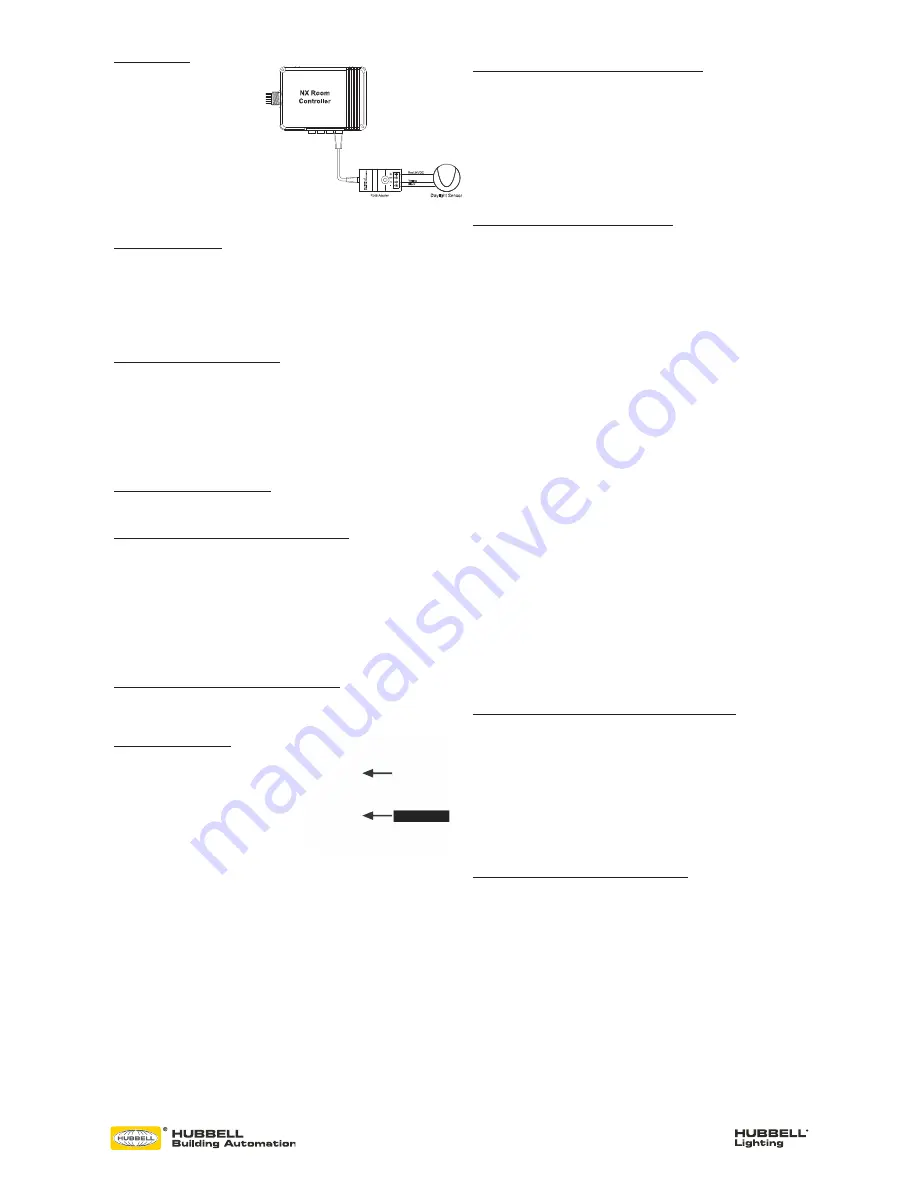
DAYLIGHT SENSOR
The model NXDS Daylight Sensor will
self configure to control Load 1 when
connected to a room controller. The
daylight sensor will become active 30
seconds after the load has been turned
on. The photocell operation can be
verified by observing Load 1 lighting
while alternately covering the photocell
(Load 1 light will be ON and bright
if dimming enabled) or exposing the
photocell to bright light (Load 1 light
will be OFF or dimmed if so enabled).
The relationship between the daylight sensor and the load(s) can be changed. See Manual
Configuration section.
MANUAL CONFIGURATION
The process of manual configuration allows certain functions to be adjusted using only the
A and B pushbuttons and LED indicators on the Room Controller. The functions that can be
adjusted are:
1. Assign loads to buttons and stations
2. Configure loads for manual ON (vacancy mode) or automatic ON operation
3. Configure loads to respond to the photocell
4. Calibrate the photocell
ENTER MANUAL CONFIGURATION MODE
To enter manual configuration mode, simultaneously press and hold buttons A and B on the
Room Controller until the A and B LEDs start to alternately blink. Release buttons A and B.
The room controller will now be in configuration mode. Load A will be ON and all other loads
will be OFF. Note, while in configuration mode no more than one load will ever be on and
the A and B buttons on the room controller will not control the loads.
Hint: If more than one load is on or pressing the A or B button switches the associated load,
you likely did not press both buttons exactly together when entering configuration mode.
Repeat the process to enter manual configuration mode.
EXIT MANUAL CONFIGURATION MODE
To exit configuration mode, simultaneously press and immediately release buttons A and B.
The room controller will resume normal operation.
ENTER MANUAL CONFIGURATION MODE FROM A SWITCH
Remove the faceplate from any wall switch and locate the rectangular opening in the plastic
bezel marked “SVC PIN”. Use a thin object such as a straightened paper clip to press the
recessed configuration button for 5 seconds. Note that the button is located slightly offset
from the opening in the bezel. The LED marked “SVC” will blink while the configuration
button is being pressed. Release the configuration button and note that one load turns on
and all other loads turn off indicating that the room is in manual configuration mode.
Hint: You may find it more convenient to remove the plastic bezil from the switch during
programming. Simply pry off using the notch at the bottom. To reattach, insert the tabs at
the top and snap into place at the bottom.
EXIT MANUAL CONFIGURATION MODE FROM A SWITCH
Press the configuration button for five seconds. Note that the LED marked “SVC” will blink
while the configuration button is being pressed. Release the configuration button. The loads
in the room will restore to the levels they were prior to entering manual configuration mode.
ASSIGN LOADS TO BUTTONS
All NXSW switch stations assume default
operation of the load(s) when they are plugged
into a Smart Port on the Room Controller. The
assignment of the loads to the buttons can easily
be changed as follows:
Enter configuration mode as described above.
Load A on the first room controller will be ON.
While load A is ON, each button that controls
that load will have a lighted LED. To unassign
control of the load from the button, press the button to extinguish the LED. To assign the
load to another button, press the switch station button to light the LED on the button. Repeat
this process for all buttons.
To advance to the next load, press and release button A on the room controller. Load A will
turn off and next load will turn ON. Repeat the assignment process above for each load.
For NXSW switch stations that do not have LED indicators, ie. NXSW-OO, NXSW-ORLO,
NXSW-RL, etc., press the ON button or the Raise button to assign the load. Press the OFF
button or the Lower button to unassign the load.
If using the Switch Station method for manual load configuration, tap the recessed
configuration button to advance to the next load as necessary.
After all loads are assigned, exit manual configuration mode. Test the button operation and
repeat the above if necessary.
CONFIGURE LOADS FOR AUTO/MANUAL ON OPERATION
Enter manual configuration mode (see above). While load A is ON, the B LED on the room
controller will indicate the current operation mode for the load. If LED B is OFF, the load
will operate in manual on (vacancy) mode. If LED B is ON, the load will operate in auto ON
mode when the motion sensor detects occupancy. Press and release button B on the room
controller to change the operation mode for the current load.
To advance to the next load, press and release button A on the room controller. Repeat the
above for all loads. When finished, exit manual configuration mode.
Hint: A load set to manual ON (vacancy mode) must be controlled by an NXSW wall
switch station otherwise the load will never turn on.
CONFIGURE LOADS FOR PHOTOCELL OPERATION
Enter manual configuration mode. While in manual configuration mode, simultaneously
press and hold buttons A and B for three seconds until the A and B LED begin to alternately
blink. This indicates the room controller has transitioned from load configuration mode into
photocell configuration mode. While in photocell configuration mode, only one load will
be ON. If the selected load has dimming capability, the light will cycle between minimum
to maximum to identify itself during the selection process. If the currently selected load is
to be controlled by the photocell, momentarily press and release button B on the room
controller. LED B will blink in a pattern to indicate the performance level for daylight
harvesting.
The blink patterns are as follows:
Double blink/pause indicates normal baseline performance (default setting)
Triple blink/pause indicates more aggressive performance, lights will dim more
Single blink/pause indicates less aggressive performance, lights will dim less
No blinking indicates that the selected load will not participate in daylight harvesting
NOTE: During this process, the load will dim to high, medium or low refelcting the
currently selected performance as indicated by the LED blink patern.
Press and release button B on the room controller to cycle through the performance choices
for the selected load. The
“more aggressive” selection will cause the light to dim more during daylight harvesting.
The “less aggressive” selection will cause the light to dim less.
Hint: If the room controller is equipped with dimming capability (NXRC-1RD or NXRC-
2RD), the photocell will assume that it’s operation will use dimming. If the room controller
does not have dimming capability (NXRC-1R or NXRC-2R), the photocell will operate in
switching mode based on a default set point of 150 foot candles.
Press and release button A on the room controller save your selection and to advance to
the next load. Repeat the above to set the performance for all loads to be controlled by
the photocell. Proceed to auto calibration of the photocell.
Hint: the above process can be used to set up multi-zone daylight harvesting in applications
where more than one row of lights are to be controlled. Simply select a more aggressive
performance for the row closest to the windows and a less aggressive performance for the
row away from the windows. Using this process it is possible to set up a room with three
zones of daylight harvesting using the triple blink setting for the row by the window, the
double blink setting for the row in the center, and the single blink setting for the row away
from the window.
RESET THE ROOM CONTROLLER TO FACTORY DEFAULT SETTINGS
Should you wish to erase all manual configuration and restore the room controller to its
factory default settings, perform the following step:
Simultaneously press and hold buttons A and B on the room controller. After a few seconds,
LED A and B will begin alternately blink. Continue to hold buttons A and B until the blink
pattern changes to a double blink pattern. Release buttons A and B. When the blinking
stops, all loads will turn on indicating the room controller has be reset to factory default
settings. After a reset, the room wil auto configure based on the connected devices.
Hint: If the installation has more than one room controller connected together in the
room, the reset process done on any one of the room controllers will reset all of the room
controllers.
RESET FACTORY DEFAULTS USING A SWITCH STATION
Remove the faceplate from any wall switch and locate the rectangular opening in the plastic
bezel marked “SVC PIN”. Use a thin object such as a straightened paper clip to press the
recessed configuration button for at least 10 seconds. Note that the button is located
slightly offset from the opening in the bezel. The LED marked “SVC” will blink while the
configuration button is being pressed. Release the configuration button and note that all
loads in the room turn on indicating that the room has been reset to factory default settings.
NXSW-ORLO
Figure 4


