Page 5
CONNECTING THE HUBBNET™ NETWORK
The NX™ Lighting Control Panel is designed to operate as part of a
NX
Networked Lighting Control system. Once programmed,
the panel will operate independently from a network connection. No software installation is required. However, a network
connection to the Area Controller is required for programming the panel. The programming interface is served from the Area
Controller and is accessible via a standard web browser on any compatible PC or computer.
The
NX
HubbNet
network is Ethernet compatible with the exception that the Cat5
HubbNet
cable carries 24 VDC as an integral
power source for certain
NX
peripheral devices. CAUTION: never plug a
HubbNet
powered network cable directly into a PC or
other Ethernet device. HCS offers accessory devices that allow
HubbNet
to be converted to standard Ethernet or Ethernet to be
converted back to
HubbNet
. Contact HCS Technical Services for additional information.
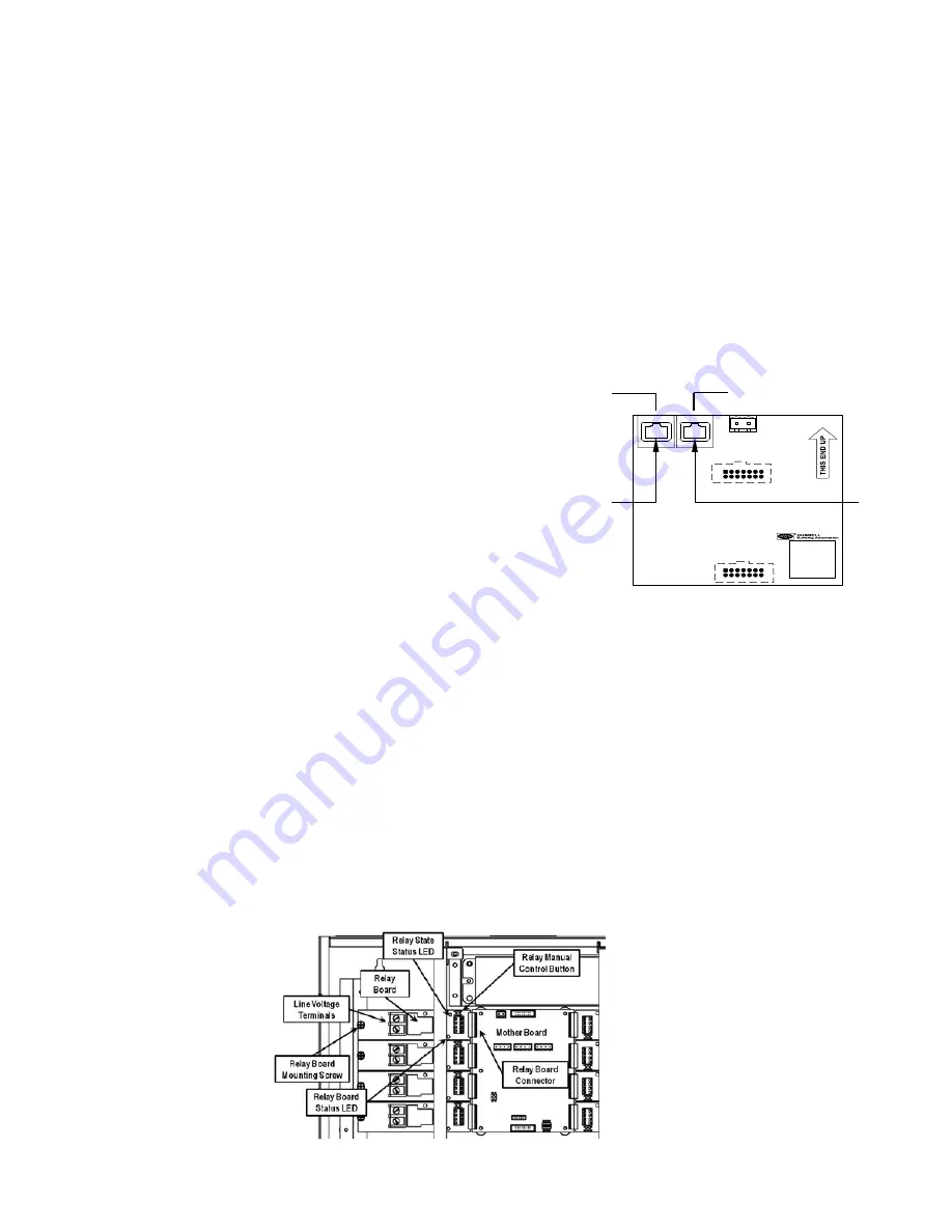
The network interface in the panel is configured to provide an IN and OUT connection point for the
HubbNet
network. This allows
a single daisy chain connection of the panels minimizing the amount of Cat5 wire required to connect the Area Controller to the
network of panels. See
Figure 4
1. Connect the Cat5 cable from the Area Controller into the
Non-Powered RJ-45 connector on the network interface board of the
first panel
2. Connect the Powered RJ-45 connector on the network interface
board of the first panel to the Non-Powered RJ-45 connector in the
next panel
3. Continue to run the network until all panels are connected.
IMPORTANT: rout the network so that there is no more than 100
meters (330 feet) of Cat5 wire between any two panels.
NOTE: Consult the factory if the installation requires a longer wire
run than 100 meters between panels.
4. With the Area Controller and the panels powered, check to be sure there is a green
LED (link light) adjacent to each RJ-45 connector. If the link light is not lit, confirm the installation of the RJ-5 connectors on the
cables using a proper testing device.
CAUTION: Never attempt to splice Cat5 cable. Use only proper industry accepted means to extend or join Cat5 Ethernet network
cable runs.
OPERATING THE PANEL
The Mother board power status LED will show continuous “green”. The Relay board status LED will turn on “green” for approximately
2 seconds and then go off. Push, but do not hold the Relay Manual Control button on each relay card to operate each relay to test
functionality. The Relay State Status LED will turn on “red” when the relay is energized and be off when the relay is un-energized. The
panel is now fully functional and ready for configuration using the web browser interface provided by the Area Controller.
FIGURE 5 - PANEL START-UP CONTROLS
FIGURE 4 - NETWORK INTERFACE
BOARD - IN - OUT
From Area
Controller or
Previous Panel
To Next Panel
Powered Out
Non Powered In


