


4
√
√
√
√
√
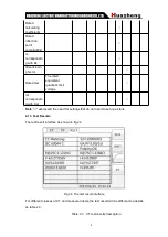
Measure CT’s
secondary winding
resistance and
excitation
characteristic,
check it’s ratio and
polarity
Fig 2.1
√
Measure CT’s
secondary burden
Fig 2.2
Note
:
The ‘
√
’ means valid, and the blank means invalid
Step:
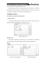
Step1. According to the CT testing project description of the table 2.1 to wiring (For all
the CT structures, please refer to the description of appendix D for the actual connection
mode)
Step 2. The other windings of the same CT should be opened; CT’s primary side to
grounding, equipment should be also to ground
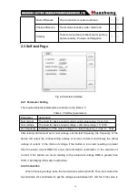
Step 3. Power on and prepare parameters Settings.
Step 4. Then switch cursor to the “start” button to start
Fig 2.1 DC resistance, excitation, ratio
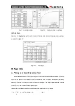
Fig 2.2 Secondary load experiment connection
experiment connection


