background image

After login, the host name of the device is displayed on the left of the prompt.

----End

12.2 Logging In to a Server Using the Integrated

Remote Console

Procedure

Step 1 Log in to the iBMC WebUI.

For details, see 

12.1 Logging In to the Server Node iBMC WebUI and CLI

.

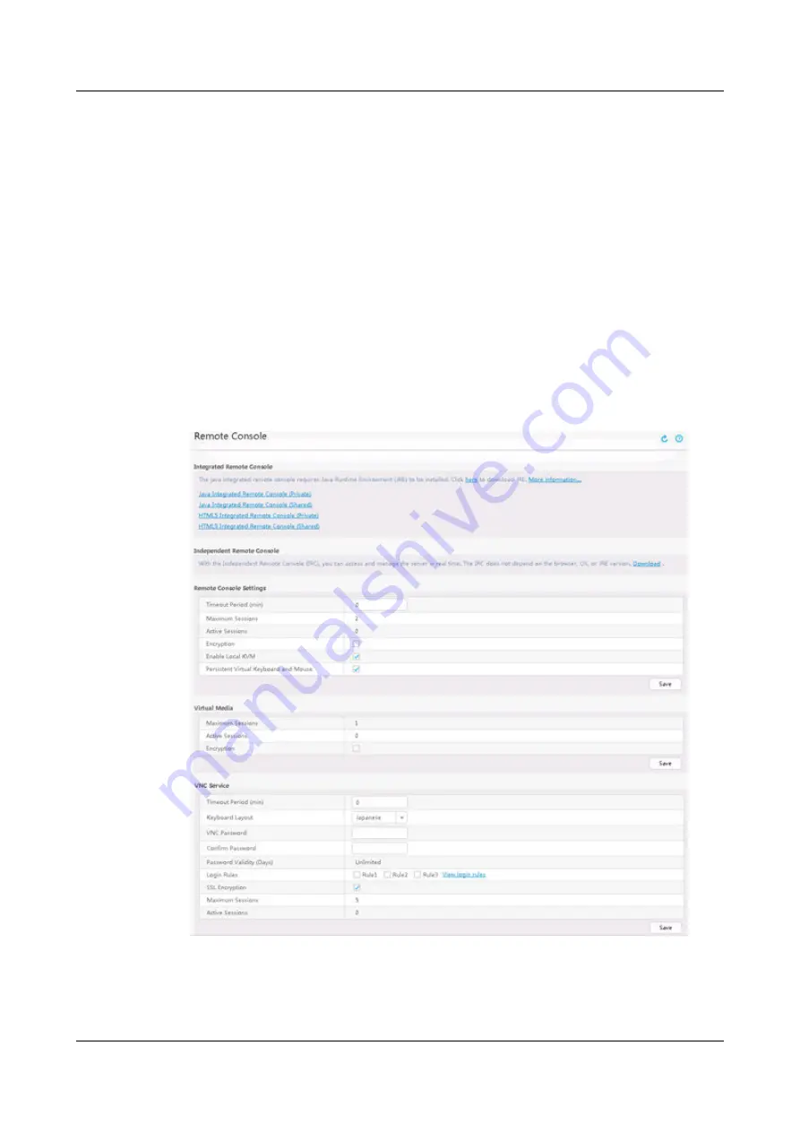
Step 2 On the menu bar, choose Remote Console.

The Remote Console page is displayed, as shown in 

Figure 12-12

.

Figure 12-12 Remote Console

Step 3 Click Java Integrated Remote Console (Private)Java Integrated Remote

Console (Shared)HTML5 Integrated Remote Console (Private), or HTML5

Integrated Remote Console (Shared).

TaiShan X6000 Server

User Guide

12 Common Operations

Issue 04 (2020-06-05)

Copyright © Huawei Technologies Co., Ltd.

92

Summary of Contents for X6000

Page 1: ...TaiShan X6000 Server User Guide Issue 04 Date 2020 06 05 HUAWEI TECHNOLOGIES CO LTD ...

Page 2: ...cribed in this document may not be within the purchase scope or the usage scope Unless otherwise specified in the contract all statements information and recommendations in this document are provided AS IS without warranties guarantees or representations of any kind either express or implied The information in this document is subject to change without notice Every effort has been made in the prep...

Page 3: ...upport engineers Technical support engineers from channel partners Enterprise administrators Symbol Conventions The symbols that may be found in this document are defined as follows Symbol Description Indicates a hazard with a high level of risk which if not avoided will result in death or serious injury Indicates a hazard with a medium level of risk which if not avoided could result in death or s...

Page 4: ...xt NOTE is used to address information not related to personal injury equipment damage and environment deterioration Change History Issue Date Description 04 2020 06 05 Added the Powered by Kunpeng label on the front panel 03 2020 03 03 Modified the description of power consumption 02 2019 03 11 Updated 2 3 Rear Panel Components 01 2018 10 30 This issue is the first official release TaiShan X6000 ...

Page 5: ...nagement 21 3 1 Server Design 21 3 2 Cooling Design 22 3 3 PSU Working Modes 23 3 4 iBMC Features 23 3 5 HMM Features 25 3 6 Management Principles 26 3 7 Management Modes 26 4 Installing the X6000 29 4 1 Installation Overview 29 4 2 Preparations 30 4 3 Unpacking Devices and the Chassis 32 4 4 Installing the Guide Rails and Chassis 34 4 4 1 Installing the L Shaped Guide Rails and Chassis 36 4 4 2 I...

Page 6: ...1 2 Logging In to the HMM CLI Through the Management Network Port of a Server Node 63 5 3 2 Changing the Initial HMM User Password 66 5 3 3 Configuring Basic HMM Data 67 5 4 Configuring a Server Node 68 6 Software and Hardware Compatibility 69 7 Internal Cabling 70 8 Troubleshooting 74 9 Electrostatic Discharge 75 9 1 Preventing Electrostatic Discharge 75 9 2 Grounding Methods 75 10 Warranty and S...

Page 7: ...12 4 Logging In to a Server Node Over a Network Port by Using PuTTY 100 12 5 Logging In to a Server Node Over a Serial Port by Using PuTTY 102 13 Support and Other Resources 104 13 1 Technical Support 104 13 2 Maintenance Tools 105 A Appendix 106 A 1 Glossary 106 A 2 Acronyms and Abbreviations 107 A 3 Sensor List 112 TaiShan X6000 Server User Guide Contents Issue 04 2020 06 05 Copyright Huawei Tec...

Page 8: ...he X6000 is oriented towards the following applications Internet and data center applications The X6000 provides customized server solutions that offer rapid deployment easy maintenance and low power consumption HPC cloud computing and ISP applications The X6000 provides a basic hardware platform that is highly reliable and provides high virtualization performance Figure 1 1 shows the X6000 Figure...

Page 9: ...led at the rear and supports rear cabling The modular design and hot swappable key components greatly improve O M efficiency Shared Architecture and High Energy Efficiency The X6000 features high energy efficiency thanks to its shared architecture The server nodes share two PSUs and four fan modules simplifying deployment and increasing PSU and fan module utilization Redundancy and Reliability The...

Page 10: ...ackplane Connectors 2 6 Disk Slot Numbers and Indicators 2 7 Fan Modules 2 8 PSUs 2 9 HMM 2 10 Physical Structure 2 1 Front Panel Components Figure 2 1 shows the front panel of the X6000 fully configured with 2U4 server nodes Figure 2 1 X6000 front panel TaiShan X6000 Server User Guide 2 Components Issue 04 2020 06 05 Copyright Huawei Technologies Co Ltd 3 ...

Page 11: ...gregation network port RJ45 1 The RJ45 port is a 1000 Mbit s Ethernet port and can be used for chassis and server node management SN The serial number SN on the label is a string that uniquely identifies a server The SN is required when you contact Huawei technical support Figure 2 2 shows the SN format Figure 2 2 SN example Table 2 2 SN description No Description 1 SN ID two characters which is 2...

Page 12: ... Z because the three letters are similar to digits 1 0 and 2 The second character indicates the month Digits 1 to 9 indicate January to September and letters A to C indicate October to December 5 Serial number six characters 6 RoHS compliance one character Y indicates environmental protection processing 7 Internal model that is product name 2 2 Front Panel Indicators and Buttons Figure 2 3 shows t...

Page 13: ...s been generated on the server node Steady green The server node is operating properly 3 UID button indicator The UID button indicator helps identify and locate a server node in a chassis You can turn on or off the UID indicator by pressing the UID button or by remotely running a command on the iBMC CLI UID indicator Off The server node is not being located Steady blue The server node has been loc...

Page 14: ...r a member drive in the RAID array is faulty 6 Hard disk activity indicator Off The hard disk is not detected or is faulty Blinking green Data is being read from the hard disk written to the hard disk or synchronized between hard disks Steady green The hard disk is inactive 7 Server health indicator Off There is no power supply or the PSU is faulty Blinking red at 1 Hz A major alarm has been gener...

Page 15: ...itted through the network port 11 Aggregation network port link status indicator Off The network port is not connected Steady green The network port has been properly connected 2 3 Rear Panel Components The X6000 contains four server nodes and two PSUs at the rear Each node supports a maximum of two PCIe cards Figure 2 4 shows the rear panel of the X6000 fully configured with 2U4 server nodes Figu...

Page 16: ...de management GE LOM port 8 A server node provides two GE LOM ports NOTICE The onboard NIC with GE electrical ports does not support interconnection with the PoE power supply device for example the PoE switch with the PoE function enabled If the NIC is forcibly connected the link communication may be abnormal or the NIC may be damaged 10GE LOM optical port 8 A server node provides two 10GE SFP por...

Page 17: ...network port is not connected Steady green The data transmission rate is 10 Gbit s NOTE 10GE optical ports do not support GE autonegotiation 2 Data transmission status indicator for an optical port Off No data is being transmitted Blinking yellow Data is being transmitted Steady yellow ethtool p tool TaiShan X6000 Server User Guide 2 Components Issue 04 2020 06 05 Copyright Huawei Technologies Co ...

Page 18: ... OS When the server is powered on holding down this button for 6 seconds will power off the server node When the server is ready to be powered on you can press this button to start the server node 4 Health indicator Off There is no power supply or the PSU is faulty Blinking red at 1 Hz A major alarm has been generated on the server Blinking red at 5 Hz A critical alarm has been generated on the se...

Page 19: ... press and hold down this button for 4 to 6 seconds to reset the iBMC 6 Data transmission status indicator for a GE electrical port Off No data is being transmitted Blinking yellow Data is being transmitted 7 Connection status indicator for a GE electrical port Off The network port is not connected Steady green The network port is properly connected 8 Data transmission status indicator for the iBM...

Page 20: ...r node is standby and the PSU is in MV6 mode The output voltage is 6 7 V The input is overvoltage or undervoltage The PSU is in deep hibernation mode Blinking green at 4 Hz under online firmware upgrade 2 5 Hard Disk Backplane Connectors Figure 2 6 shows the connectors on the disk backplane Figure 2 6 Disk backplane 1 Backplane signal cable connector J30 2 Slimline connector J17 3 Slimline connect...

Page 21: ...ble 2 6 X6000 configuration Disk Backplane Maximum Front Disks Disk Management Mode 24 bay SAS SATA disk backplane 24 SAS HDD SATA SSD 1 RAID controller card Directly connected to the CPU SoftRAID 2 6 2 Disk Indicators Figure 2 8 shows the disk indicators Figure 2 8 Disk indicators Table 2 7 describes the disk indicators TaiShan X6000 Server User Guide 2 Components Issue 04 2020 06 05 Copyright Hu...

Page 22: ...n to the disk or synchronized between disks Steady green The disk is inactive 2 7 Fan Modules The X6000 uses four 8080 counter rotary fans with high wind pressure to improve the cooling capability of the server The management module adjusts the fan speed based on the server node operating status to implement intelligent heat dissipation and one fan failures are allowed Figure 2 9 shows a fan modul...

Page 23: ...t live wires provide a double pole fuse Figure 2 10 shows an AC PSU Figure 2 10 AC PSU The PSU has a latch an AC power input socket and an operating status indicator as shown in Figure 2 11 Figure 2 11 AC PSU panel TaiShan X6000 Server User Guide 2 Components Issue 04 2020 06 05 Copyright Huawei Technologies Co Ltd 16 ...

Page 24: ...aggregation network port on the chassis front panel through the aggregation module Through this network port users can log in to the iBMC of each server node Users can also log in to the iBMC of a server node through the management network port provided by the server node Figure 2 12 shows an aggregation module Figure 2 12 Aggregation module Figure 2 13 shows an HMM TaiShan X6000 Server User Guide...

Page 25: ...aggregation module 1 Connection status indicator 2 Aggregation network port 3 Data transmission status indicator 2 10 Physical Structure Figure 2 15 shows the system components of the X6000 TaiShan X6000 Server User Guide 2 Components Issue 04 2020 06 05 Copyright Huawei Technologies Co Ltd 18 ...

Page 26: ...s means that only one port for the out of band management system interfaces with external devices NOTE Before configuring the aggregation network port set the management network port mode to aggregation mode on the server node 6 Disk backplane Provides power cable connectors and data transmission channels for disks The X6000 supports the backplane for 2 5 inch SAS SATA disks 7 Fan backplane Drives...

Page 27: ... to the server 11 PSU 2 x 1500 W enhanced AC PSUs compatible with 240 HVDC NOTE The X6000 PSUs support 1 1 redundancy mode only when the server power is lower than that of a single PSU If the input voltage is between 100 V and 120 V the working power of each PSU will decrease to 1000 W If the input power is between 200 V and 240 V or 240 V HVDC the working power is 1700 W TaiShan X6000 Server User...

Page 28: ...issipation and power supply of common components as well as chassis assets You can log in to the iBMC WebUI using the management port of a server node or the aggregation port 3 1 Server Design 3 2 Cooling Design 3 3 PSU Working Modes 3 4 iBMC Features 3 5 HMM Features 3 6 Management Principles 3 7 Management Modes 3 1 Server Design The X6000 is a next generation server that has the following featu...

Page 29: ...om the front panel of the chassis delivers the cool air through the disks fan modules backplane to the four server nodes and then to the processors and dual in line memory modules DIMMs and then exhausts air from the rear The X6000 uses four 8080 counter rotary fans with high wind pressure to provide industry leading cooling and power saving capabilities The 8080 fans use DTS 2 0 control to ensure...

Page 30: ...X6000 In this mode if one PSU fails the other PSU takes over so that the X6000 works properly Non Redundancy Mode One PSU cannot meet the load requirements of the X6000 In this mode two PSUs work together and if one PSU fails services on the X6000 may be interrupted NOTICE Before replacing or adding a component calculate the new system power consumption and determine whether the PSUs can meet the ...

Page 31: ...te server simplifying OS installation The virtual DVD ROM drive supports a maximum transmission rate of 8 MB s WebUI Provides a visual WebUI to simplify configuration and operation The iBMC WebUI supports the following browsers Internet Explorer 9 0 10 0 11 0 Mozilla Firefox 26 0 or later Chrome 21 0 or later Safari 8 0 Compatible JRE environments are as follows JRE 1 7 0 JRE 1 8 0 Fault reproduct...

Page 32: ...th any standard management system IPMI V2 0 CLI Server fault detectio n Detects and locates hardware faults accurate down to components Server alarm manage ment Supports alarm management and reports alarms in various ways such as syslog service to ensure uninterrupted 24 7 system operation Chassis asset manage ment Provides intelligent asset management Intellige nt power manage ment Uses the power...

Page 33: ...ls for controlling the fan speed and eight TACH signals for detecting the fan speed The HMM uses Huawei speed adjustment algorithms to determine a fan speed based on the temperature of temperature sensitive components and the environment and sends fan speed data to the fan backplane The fan backplane also receives fan speed signals from the fan modules to monitor the fan operating status and repor...

Page 34: ...able is routed from a server node default configuration in the BIOS as shown in Figure 3 2 In NC SI mode the management network cable can also be used as a service network cable and connected to a service network port Figure 3 2 Point to point cabling Aggregation management cabling A server node is accessed through the aggregation network port over the out of band management network The network ca...

Page 35: ...Figure 3 3 Aggregation management cabling TaiShan X6000 Server User Guide 3 System Architecture and Management Issue 04 2020 06 05 Copyright Huawei Technologies Co Ltd 28 ...

Page 36: ...ls and Chassis 4 5 Connecting Cables 4 6 Verifying the Installation 4 1 Installation Overview Understand the entire installation process before installing the X6000 Figure 4 1 shows the process for installing the X6000 TaiShan X6000 Server User Guide 4 Installing the X6000 Issue 04 2020 06 05 Copyright Huawei Technologies Co Ltd 29 ...

Page 37: ...and negotiates with the customer to determine the suppliers of these tools The multimeter must be calibrated before use Table 4 1 Tools Tool Picture Name Operation Instructions Floating nut hook Used to install a floating nut on a rack mounting bar TaiShan X6000 Server User Guide 4 Installing the X6000 Issue 04 2020 06 05 Copyright Huawei Technologies Co Ltd 30 ...

Page 38: ...t cable ties Measuring tape Used to measure distance Multimeter Used to measure resistance and voltage and to check connectivity ESD wrist strap Used to prevent ESD damage Cable tie Used to bind cables ESD gloves Used to prevent ESD damage TaiShan X6000 Server User Guide 4 Installing the X6000 Issue 04 2020 06 05 Copyright Huawei Technologies Co Ltd 31 ...

Page 39: ... also obtain product documents from Huawei Enterprise support website http enterprise huawei com Table 4 2 DVD and documents Category Description DVD Driver DVD contains network interface card NIC chip drivers Document Documentation bag contains the TaiShan 100 Server Quick Start Guide Model X6000 4 3 Unpacking Devices and the Chassis Procedure Step 1 TaiShan X6000 Server User Guide 4 Installing t...

Page 40: ...vice packing case to the equipment room and take away the pallet truck Step 3 Unpack the devices 1 Use a box cutter to cut the pressure sensitive adhesive tape on the packing case When using a box cutter to unpack a packing case ensure that the knife edge is of proper protrusion to avoid injuring hands or damaging the device in the packing case 2 Remove the packing case of the chassis as shown in ...

Page 41: ...nstall the chassis in a standard cabinet Prerequisites 1 Precautions Three persons are required to move and install a chassis Three persons are required to hold the left and right edges of an empty chassis and exert even force Do not hold the upper edge of the chassis because this may damage the chassis shell Each chassis must be installed on the guide rails in a cabinet Do not stack chassis in a ...

Page 42: ...abinet ESD gloves used to prevent ESD damage when you move a chassis Installation Description Guide Rail Installation Requirements Before installing guide rails you need to determine the positions of guide rails based on the configuration scheme NOTICE The middle of two adjacent square holes with small spacing is the boundary of two Us See Figure 4 3 The boundary between Us is used as a reference ...

Page 43: ...nd screws are used together to secure the chassis The boundary of two Us is indicated by the smaller spacing between two adjacent square holes as shown in Figure 4 4 The boundary between Us is used as a reference for calculating the device installation space Figure 4 4 Spacing of 1U on a mounting bar of a cabinet 2 Put the lower end of a floating nut into the installation hole at the front of the ...

Page 44: ...hile keeping the guide rail in contact with the mounting bars in the cabinet as shown in Figure 4 6 Figure 4 6 Installing an L shaped guide rail 2 Tighten the screws 3 Install the other guide rail using the same method TaiShan X6000 Server User Guide 4 Installing the X6000 Issue 04 2020 06 05 Copyright Huawei Technologies Co Ltd 37 ...

Page 45: ...4 4 2 Installing the Adjustable Guide Rails and Chassis Adjustable guide rails are for cabinets where the distance between the front and rear mounting bars is 543 5 848 5 mm 21 40 33 41 in Procedure Step 1 Install adjustable guide rails 1 Place a guide rail horizontally in the planned position while keeping the guide rail in contact with the mounting bars in the cabinet and hook the guide rail to ...

Page 46: ...ll M6 screws at the rear of the adjustable guide rails to make the server more shockproof and secure 4 Install the other guide rail using the same method Figure 4 8 Installing an adjustable guide rail Step 2 Install the X6000 1 Lift the X6000 on both sides This task requires at least three persons 2 Place the X6000 on the guide rails and push it into the cabinet See 1 in Figure 4 9 TaiShan X6000 S...

Page 47: ...98 in Procedure Step 1 Install holding rails 1 Press down on the spring at the front end of the holding rail and pull out the hook See 1 and 2 in Figure 4 10 2 Insert the positioning pins into square holes at the rear of the cabinet See 3 in Figure 4 10 3 Align the front end of the rail with a square hole and push the holding rail forward until it snaps into place See 4 in Figure 4 10 4 Push the h...

Page 48: ...n installing a server 1 Pull out an inner rail from a holding rail until the inner rail cannot move push the release lever upward and remove the inner rail from the holding rail See 1 and 2 in Figure 4 11 TaiShan X6000 Server User Guide 4 Installing the X6000 Issue 04 2020 06 05 Copyright Huawei Technologies Co Ltd 41 ...

Page 49: ... the inner rail with the fastening screws on one side of the server and push the inner rail forward until it is secured to the server as shown in Figure 4 12 TaiShan X6000 Server User Guide 4 Installing the X6000 Issue 04 2020 06 05 Copyright Huawei Technologies Co Ltd 42 ...

Page 50: ...ails with the holding rails and push the server into the cabinet as shown in Figure 4 13 At least three people are required to lift the server from both sides TaiShan X6000 Server User Guide 4 Installing the X6000 Issue 04 2020 06 05 Copyright Huawei Technologies Co Ltd 43 ...

Page 51: ...lipped into the middle rail the rolling balls and the holding rail may be damaged as shown in 2 and 3 in Figure 4 14 Figure 4 14 Clipping the inner rail into the middle rail 4 Press the release levers on both sides and push the server into the cabinet until the server cannot move forward as shown in Figure 4 15 TaiShan X6000 Server User Guide 4 Installing the X6000 Issue 04 2020 06 05 Copyright Hu...

Page 52: ...et 5 Tighten the captive screws on the mounting ears to secure the server as shown in Figure 4 16 Figure 4 16 Securing a server TaiShan X6000 Server User Guide 4 Installing the X6000 Issue 04 2020 06 05 Copyright Huawei Technologies Co Ltd 45 ...

Page 53: ... is complete connect a network cable a VGA cable or USB devices as required Connect the power cables and power on the X6000 End 4 5 Connecting Cables 4 5 1 Precautions NOTICE Before connecting power cables to the devices in a cabinet ensure that the power distribution cabinet PDC in the equipment room and the power distribution box PDB in the cabinet are switched off Table 4 4 describes the precau...

Page 54: ...abinet Bind the cables along the inner sides of the mounting bars on both sides of the cabinet For details see 4 5 7 Laying Out Cables Verifying cable connections Check that all cables are correctly connected and connectors are properly installed 4 5 2 Connecting a Power Cable Precautions Connect power cables securely and maintain sufficient slack for the power cables Use dedicated power cables to...

Page 55: ...er cable using a velcro strap See Figure 4 19 Figure 4 19 Securing a power cable 3 Connect the other end of the power cable to the busbar of the cabinet TaiShan X6000 Server User Guide 4 Installing the X6000 Issue 04 2020 06 05 Copyright Huawei Technologies Co Ltd 48 ...

Page 56: ... one RJ45 serial port and three USB 2 0 compatible with USB 1 1 ports The port functions are as follows DB 15 VGA connector connects to the VGA port on the client One RJ45 serial port used for commissioning This port can be set as the iBMC serial port using the CLI Two USB 2 0 connectors connect to the USB keyboard and mouse on the client to provide KVM functions One USB 2 0 connector connects to ...

Page 57: ...ure 4 21 End 4 5 4 Connecting an Optical Cable Precautions Install an optical module in an optical port before connecting the optical cable To avoid damage to an optical module do not exert excessive force to remove or insert it To avoid damage to an optical module do not frequently or quickly remove or insert it Procedure Step 1 Wear an ESD wrist strap or ESD gloves Step 2 Remove the dust proof c...

Page 58: ...buckle of the optical module is fully closed Step 4 Remove the fiber protective cap See 3 in Figure 4 22 Do not look into the optical port without any eye protection Step 5 Horizontally insert the optical cable into the optical module until you hear a click See 4 in Figure 4 22 End TaiShan X6000 Server User Guide 4 Installing the X6000 Issue 04 2020 06 05 Copyright Huawei Technologies Co Ltd 51 ...

Page 59: ...network cable connector is intact and the pins have no sundries or deformation Server nodes provide GE service ports Figure 4 23 shows how to connect an Ethernet cable to a service GE port Figure 4 23 Connecting an Ethernet cable to a GE service port Connecting an Ethernet Cable to a Management Network Port A server node provides a management network port on its front panel Figure 4 24 shows how t...

Page 60: ...lded twisted pair STP Ethernet cable to connect to the management network port to achieve high network performance and electromagnetic compatibility EMC Before installing a network cable to a network port check that the network cable connector is intact and the pins have no sundries or deformation Figure 4 25 shows how to connect the aggregation management network cable TaiShan X6000 Server User G...

Page 61: ...ation layers of the cables Ensure that the length of cable ties for binding the cables is appropriate Do not connect two or more cable ties together After properly binding the cables trim any excess lengths of the cable ties and ensure that the cuts are neat and smooth Cables must be properly routed supported and fixed in the cable trough so that the cables can be securely connected to the termina...

Page 62: ...es at the rear of the cabinet and bind them to the right cable trough Alternatively route them at the front of the cabinet and bind them to the cable troughs on both sides of the cabinet Choose overhead or underfloor cabling for service data cables based on equipment room conditions such as the cabling mode overhead or underfloor cabling used by signal cables Place the connectors of all service da...

Page 63: ...re lowered Step 3 Check that all PSUs are properly installed and their handles are latched Step 4 Check that the hard disks are properly installed and their ejector levers are lowered Step 5 Check that the Hyper Management Module HMM is properly installed End 4 6 2 Verifying Cable Connections Scenario Verify cable connections in any of the following scenarios During routine maintenance During trou...

Page 64: ...cted Network cables Network cables are correctly connected to the specified management or service network port End 4 6 3 Powering On the Chassis Scenario Devices and cables are properly installed Procedure Step 1 Switch on the AC power distribution box PDB that corresponds to the power cable of the chassis Step 2 Switch on the busbar of the cabinet Step 3 Observe the status of chassis indicators T...

Page 65: ...All fans are properly operating without sharp noises The hard disk activity indicators PSU operating status indicators and server health indicator are steady green or blinking green Step 3 Check the server node operating status The status indicator on each server node panel is steady green or blinking green End TaiShan X6000 Server User Guide 4 Installing the X6000 Issue 04 2020 06 05 Copyright Hu...

Page 66: ...e X6000 after it is installed Figure 5 1 shows the prcess for configuring the X6000 Figure 5 1 Configuration process 5 2 Default Data To ensure system security change your initial password upon the first login and change the password periodically TaiShan X6000 Server User Guide 5 Configuring the X6000 Issue 04 2020 06 05 Copyright Huawei Technologies Co Ltd 59 ...

Page 67: ...Slot 4 10 10 1 104 255 255 255 0 5 3 Configuring the HMM 5 3 1 Logging In to the HMM CLI The HMM does not have a WebUI You can use the following methods to log in to the HMM CLI to manage servers 5 3 1 1 Logging In to the HMM CLI Through the Aggregation Network Port Procedure Step 1 Connect a PC to the aggregation network port Connect the PC to the aggregation network port using a network cable Se...

Page 68: ...gation network port Run the Ping Aggregation network port IP address command on the PC CLI to check whether the PC can properly communicate with the server Step 3 Log in to the HMM CLI 1 On the PC double click PuTTY exe The PuTTY Configuration window is displayed as shown in Figure 5 3 TaiShan X6000 Server User Guide 5 Configuring the X6000 Issue 04 2020 06 05 Copyright Huawei Technologies Co Ltd ...

Page 69: ...d under Saved Sessions to log in to the server the next time 3 Click Open The PuTTY window is displayed If this is your first login to the server the PuTTY Security Alert dialog box is displayed Click Yes to proceed If the account entered during server login is incorrect reconnect PuTTY 4 Enter the user name and password After login the host name of the device is displayed on the left of the promp...

Page 70: ... of the server node Connect the PC to the iBMC management network port on the server node using a network cable See Figure 5 4 Figure 5 4 Connecting a cable to the management network port of a server node Step 2 Set the IP address of the PC 1 Set the IP address subnet mask or route of the PC and ensure that the PC can communicate with the iBMC management network port Run the Ping iBMC management n...

Page 71: ... 2 Set HMM SSH NAT to On and Port to 30022 and click Save See Figure 5 5 Figure 5 5 Enabling transparent transmission Step 5 Log in to the HMM CLI 1 On the PC double click PuTTY exe The PuTTY Configuration window is displayed as shown in Figure 5 6 TaiShan X6000 Server User Guide 5 Configuring the X6000 Issue 04 2020 06 05 Copyright Huawei Technologies Co Ltd 64 ...

Page 72: ...he next time 3 Click Open The PuTTY window is displayed If this is your first login to the server the PuTTY Security Alert dialog box is displayed Click Yes to proceed If the account entered during server login is incorrect reconnect PuTTY 4 Enter the user name and password The command output is as follows login as Administrator huawei Using keyboard interactive authentication Password Last login ...

Page 73: ...1 2016 17 56 50 IPMB Address 0x10 Product INFO Product ID 0x0003 Product Name MM630 Mother Board INFO Mainboard BoardID 0x0066 Mainboard PCB A FAN Board INFO BC21FIMCA BoardID 0x0056 BC21FIMCA PCB A BC21FIMCA CPLD Version U0 N A Backplane INFO BC21BKPL BoardID 0x0044 BC21BKPL PCB A End 5 3 2 Changing the Initial HMM User Password Procedure Step 1 Log in to the HMM CLI For details see 5 3 1 Logging...

Page 74: ...address NOTICE After the IP address is configured the new IP address takes effect immediately and you must use the new IP address to log in again 1 Log in to the HMM CLI For details see 5 3 1 Logging In to the HMM CLI 2 On the HMM CLI run one of the following commands Setting an IPv4 address ipmcset d ipaddr v ipaddr mask gateway Setting an IPv6 address ipmcset d ipaddr6 v ipaddr6 prefixlen gatewa...

Page 75: ...h of the network port to be configured 0 to 128 gateway6 Specifies the IPv6 gateway address of the network port to be configured The value is an IPv6 address in the format of xxxx xxxx xxxx xxxx xxxx xxxx xxxx xxxx When multiple continuous xxxx are 0 the value is in the format of xxxx xxxx For example 2001 0000 000 0000 0000 0000 0 000 0001 can be written as 2001 0001 An IPv6 address can contain o...

Page 76: ...etails about the software and hardware supported by the X6000 see the Intelligent Computing Compatibility Checker TaiShan X6000 Server User Guide 6 Software and Hardware Compatibility Issue 04 2020 06 05 Copyright Huawei Technologies Co Ltd 69 ...

Page 77: ...ing ear cabling No Description BOM Number 1 Signal cable for connecting the indicator board on the right mounting ear to the backplane J30 04051340 001 2 Signal cable for connecting the indicator board on the left mounting ear to the backplane J31 04051340 001 TaiShan X6000 Server User Guide 7 Internal Cabling Issue 04 2020 06 05 Copyright Huawei Technologies Co Ltd 70 ...

Page 78: ... BOM Numbe r 1 Signal cable for connecting the aggregation module to the HMM J6 040518 57 Cabling from the Fan and PSU Backplanes to the HMM Figure 7 3 shows the cabling from the fan and PSU backplanes to the HMM TaiShan X6000 Server User Guide 7 Internal Cabling Issue 04 2020 06 05 Copyright Huawei Technologies Co Ltd 71 ...

Page 79: ...4051340 001 2 Signal cable for connecting a fan backplane J6 to the HMM J11 04051340 002 3 Signal cable for connecting a fan backplane J1 to the HMM J1 04150626 Hard Disk Backplane Cabling Figure 7 4 shows the cabling of the hard disk backplane TaiShan X6000 Server User Guide 7 Internal Cabling Issue 04 2020 06 05 Copyright Huawei Technologies Co Ltd 72 ...

Page 80: ... connecting the hard disk backplane J13 to the system backplane J24 040518 52 3 Signal cable for connecting the hard disk backplane J6 to the system backplane J21 040518 52 4 Signal cable for connecting the hard disk backplane J39 to the system backplane J18 040518 52 TaiShan X6000 Server User Guide 7 Internal Cabling Issue 04 2020 06 05 Copyright Huawei Technologies Co Ltd 73 ...

Page 81: ...If a fault occurs on a server collect logs for fault diagnosis Fault diagnosis Fault diagnosis rules and tools help Huawei technical support engineers and maintenance engineers to analyze and rectify faults according to alarms and hardware fault symptoms Software and firmware upgrade Software and firmware upgrade packages can be downloaded by server model and installed as needed Preventive mainten...

Page 82: ...roduct Do not touch pins or circuits 9 2 Grounding Methods Use one or more of the following grounding methods when handling electrostatic sensitive components Use a wrist strap that connects to a grounded workplace or server chassis The wrist strap must be elastic and the cable resistance must be at least 1 MΩ 10 Ensure that the wrist strap makes maximum contact with bare skin Use heel straps toe ...

Page 83: ...nditions including the available services response time terms of service and disclaimer The warranty terms and conditions may vary by country and some services and or parts may not be available in all countries For details about warranty services in your country contact Huawei technical support or the local Huawei office For more information visit Maintenance Warranty 10 2 Safety For details see H...

Page 84: ...server chassis for unified chassis management One management port on each server node PSUs 2 x 1500 W enhanced AC PSUs compatible with 240 HVDC NOTE The X6000 PSUs support 1 1 redundancy mode only when the server power consumption is lower than that of a single server If the input power is between 100 V and 120 V the working power of each PSU will decrease to 1000 W If the input power is between 2...

Page 85: ...cations Table 11 2 provides the specifications of XR320 high density nodes supported by the X6000 Table 11 2 Server node specifications Type Model Specifications Chassis X6000 A 2U chassis housing four server nodes Server node XR320 high density node It provides the following hardware components Two Hi1616 processors Up to 16 DDR4 DIMMs 6 x 2 5 inch SAS SATA disks 2 x half height half length stand...

Page 86: ...mperature ranging from 5 C to 30 C 41 F to 86 F Relative humidity non condensin g Operating humidity 8 to 90 Storage humidity 5 to 95 Maximum temperatu re fluctuation rate 20 C h 36 F h Altitude Operating altitude 3000 m 9842 52 ft NOTE When the server is used at an altitude from 900 m 2952 76 ft to 3000 m 9842 52 ft the highest operating temperature decreases by 1 C 1 8 F for every increase of 30...

Page 87: ...ctual sound levels generated when the server is operating vary depending on the server configuration workload and ambient temperature Corrosive air pollutant Corrosion rate of the copper test piece 300 Å month in compliance with the ANSI ISA 71 04 2013 gaseous corrosion level G1 Corrosion rate of the silver test piece 200 Å month Particulate pollutant The ISO14664 1 Class 8 requirements are met Yo...

Page 88: ...ode Over a Serial Port by Using PuTTY 12 1 Logging In to the Server Node iBMC WebUI and CLI The iBMC provides a WebUI and CLI for server node management 12 1 1 Logging In to the iBMC CLI or WebUI of a Server Node Through the iBMC Management Network Port Data IP address of the iBMC management network port on the server node User name and password of the server node iBMC TaiShan X6000 Server User Gu...

Page 89: ... you log in to the iBMC CLI or WebUI through the iBMC management network port the management network port mode must be the fixed or automatic mode Step 1 Connect a PC to the management network port on the server node Connect the PC to the iBMC management network port on the server node using a network cable See Figure 12 1 Figure 12 1 Connecting a cable to the management network port of a server n...

Page 90: ...browser enter the IP address of the iBMC management network port in the address box and press Enter 2 On the login page shown in Figure 12 2 enter the user name and password and click Log In Figure 12 2 Logging in to the iBMC Change the default password when logging in to the iBMC for the first time Step 4 Log in to the iBMC CLI of the server node 1 On the PC double click PuTTY exe The PuTTY Confi...

Page 91: ...rd under Saved Sessions to log in to the server the next time 3 Click Open The PuTTY window is displayed If this is your first login to the server node the PuTTY Security Alert dialog box is displayed Click Yes to proceed If the account entered during server node login is incorrect reconnect PuTTY 4 Enter the user name and password After login the host name of the device is displayed on the left o...

Page 92: ...a PC to the aggregation network port Connect the PC to the aggregation network port using a network cable See Figure 12 4 Before configuring port aggregation ensure that the management port is connected with a network cable Otherwise the management connection will be interrupted after the configuration Figure 12 4 Connecting a cable to the aggregation network port Step 2 Connect the PC to the iBMC...

Page 93: ... check whether the PC can properly communicate with the server Step 4 Enable the port aggregation function for the server node Enable network port aggregation by using the iBMC WebUI or CLI Method 1 Enable network port aggregation on the iBMC WebUI i Log in to the iBMC WebUI select Fixed as the network port mode on the NetWork Settings page and select a network port under Aggregation Port See Figu...

Page 94: ...et d netmode v 1 Set net mode Manual successfully iii Run the following command to enable network port aggregation iBMC ipmcset d activeport v 3 Set active port successfully Enable network port aggregation on the BIOS a When the screen shown in Figure 12 7 is displayed press Delete or F4 to start the BIOS Setup Utility TaiShan X6000 Server User Guide 12 Common Operations Issue 04 2020 06 05 Copyri...

Page 95: ...from the network Enter the password in the displayed dialog box b Choose Advanced IPMI iBMC Configuration iBMC Configuration and select iBMC NetWork Mode See Figure 12 8 and Figure 12 9 TaiShan X6000 Server User Guide 12 Common Operations Issue 04 2020 06 05 Copyright Huawei Technologies Co Ltd 88 ...

Page 96: ...ng options are displayed Dedicated Use the dedicated port as the iBMC network port OnBoard Shared Use a service network port on the LAN on motherboard LOM as the iBMC network port TaiShan X6000 Server User Guide 12 Common Operations Issue 04 2020 06 05 Copyright Huawei Technologies Co Ltd 89 ...

Page 97: ...You are advised to configure a virtual local area network VLAN for the management network port for security purposes if Fixed or Automatic is selected and a LOM network port is configured d Select Aggregation and press Enter Enable port aggregation for each server node Step 5 Log in to the iBMC WebUI of the server node 1 Open a browser enter the IP address of the iBMC management network port in th...

Page 98: ... Host Name or IP address and Saved Sessions and click Save You can double click the saved record under Saved Sessions to log in to the server the next time 3 Click Open The PuTTY window is displayed If this is your first login to the server node the PuTTY Security Alert dialog box is displayed Click Yes to proceed If the account entered during server node login is incorrect reconnect PuTTY 4 Enter...

Page 99: ...e iBMC WebUI and CLI Step 2 On the menu bar choose Remote Console The Remote Console page is displayed as shown in Figure 12 12 Figure 12 12 Remote Console Step 3 Click Java Integrated Remote Console Private Java Integrated Remote Console Shared HTML5 Integrated Remote Console Private or HTML5 Integrated Remote Console Shared TaiShan X6000 Server User Guide 12 Common Operations Issue 04 2020 06 05...

Page 100: ...on the server by using the iBMC The users can see each other s operations HTML5 Integrated Remote Console Private Only one local user or VNC user can connect to the server OS by using the iBMC HTML5 Integrated Remote Console Shared Two local users or five VNC users can concurrently connect to the server OS and perform operations on the server by using the iBMC The users can see each other s operat...

Page 101: ...2 32 bit or 64 bit Windows Server 2012 64 bit Step 1 Configure an IP address for the client PC to enable communication between the client and the Server node The IP address configured and the iBMC management network port IP address must be on the same network segment Step 2 Double click KVM exe A dialog box similar to the one shown in Figure 12 15 is displayed TaiShan X6000 Server User Guide 12 Co...

Page 102: ...168 100 1 444 When the port number is the default port number 443 the port number can be left blank Step 4 Select a login mode and click Connect Shared Mode allows two users to access and manage a server node at the same time The two users can see each other s operations Private Mode allows only one user to access and manage a server node at a time Information shown in Figure 12 16 is displayed Fi...

Page 103: ...untu 14 04 LTS and Ubuntu 16 04 LTS Step 1 Configure an IP address for the client PC to enable communication between the client and the iBMC The IP address configured and the iBMC management network port IP address must be on the same network segment Step 2 Open the console and set the folder where the IRC is stored as the working folder Step 3 Run the chmod 777 KVM sh command to set the permissio...

Page 104: ...168 100 1 444 When the port number is the default port number 443 the port number can be left blank Step 6 Select a login mode and click Connect Shared Mode allows two users to access and manage a server node at the same time The two users can see each other s operations Private Mode allows only one user to access and manage a server node at a time Information shown in Figure 12 19 is displayed Fi...

Page 105: ...ted OS Mac OS X El Capitan Step 1 Configure an IP address for the client PC to enable communication between the client and the iBMC The IP address configured and the iBMC management network port IP address must be on the same network segment Step 2 Open the console and set the folder where the IRC is stored as the working folder Step 3 Run the chmod 777 KVM sh command to set the permission for the...

Page 106: ...168 100 1 444 When the port number is the default port number 443 the port number can be left blank Step 6 Select a login mode and click Connect Shared Mode allows two users to access and manage a server node at the same time The two users can see each other s operations Private Mode allows only one user to access and manage a server node at a time Information shown in Figure 12 22 is displayed Fi...

Page 107: ... 4 Logging In to a Server Node Over a Network Port by Using PuTTY Procedure Step 1 Set an IP address and a subnet mask or add route information for the PC so that the PC can properly communicate with the server You can run the Ping 10 10 1 104 IP address of the destination server node or HMM command on the PC command line interface CLI to check the communication between the PC and the server Step ...

Page 108: ...onnection type Retain the default value SSH Close window on exit Retain the default value Only on clean exit Set Host Name and Saved Sessions and click Save You can locate and double click the saved record in Saved Sessions to log in to the server in future Step 4 Click Open The PuTTY window and login as are displayed and you need to enter a user name TaiShan X6000 Server User Guide 12 Common Oper...

Page 109: ...displayed Step 2 In the navigation tree choose Connection Serial Step 3 Set the login parameters The following are example login parameters Serial line to connect to COMn Speed baud 115200 Data bits 8 Stop bits 1 Parity None Flow control None n indicates the serial port number and the value is an integer Step 4 In the navigation tree choose Session Step 5 Set Connection type to Serial and set Clos...

Page 110: ...lert window is displayed If you trust this site click Yes Then the PuTTY window is displayed If the entered user name is incorrect during server node login you must connect to PuTTY again Step 7 Enter a user name and password to log in After login the server host name is displayed to the left of the prompt End TaiShan X6000 Server User Guide 12 Common Operations Issue 04 2020 06 05 Copyright Huawe...

Page 111: ...gent Q A system for quick learning about products Huawei Enterprise Support Community Server for learning and discussion News For notices about product life cycles warnings and updates visit Product News Cases Learn server applications at the Knowledge Base Huawei Technical Support If a fault persists after taking the above measures contact technical support at your local Huawei office If a local ...

Page 112: ... servers Table 13 1 Software tools for routine maintenance Tool Server and Version Description FusionServer Tools SmartKit See the FusionServer Tools 2 0 SmartKit User Guide SmartKit contains tools required for operations such as batch deployment maintenance and upgrade of server devices Download link FusionServer Tools TaiShan X6000 Server User Guide 13 Support and Other Resources Issue 04 2020 0...

Page 113: ...or lever An item or part on the panel used to insert or remove a server node Ethernet A baseband local area network LAN architecture developed by Xerox Corporation in cooperation with DEC and Intel Ethernet uses the carrier sense multiple types of access collision detection CSMA CD access methods and supports data transfer rates of 10 Mbit s on multiple cables The Ethernet specification is the bas...

Page 114: ... provide higher storage and redundancy performance than a single physical disk redundan cy The ability of a system to keep functioning normally in the event of a device failure by having a backup device automatically replace the faulty one S SEL System event log A non volatile storage area and the associated ports that store system platform events for later retrieval server A special computer prov...

Page 115: ... DEMT Dynamic Energy Management Technology DIMM dual in line memory module DRAM dynamic random access memory DVD digital video disc E ECC Error Checking and Correcting ECMA European Computer Manufacturer Association EDB execute disable bit EN European Efficiency ERP Enterprise Resource Planning ETS European Telecommunication Standards F FB DIMM fully buffered DIMM FC Fibre Channel FCC Federal Comm...

Page 116: ... Center IEC International Electrotechnical Commission IEEE Institute of Electrical and Electronics Engineers IGMP Internet Group Message Protocol iBMC Integrated Baseboard Management Controller IOPS input output operations per second IP Internet Protocol IPC Intelligent Power Capability IPMB Intelligent Platform Management Bus IPMI Intelligent Platform Management Interface K KVM keyboard video and...

Page 117: ...ID Redundant Array of Independent Disks RAS Reliability Availability and Serviceability RDIMM registered dual in line memory module REACH Registration Evaluation and Authorization of Chemicals RJ45 Registered Jack 45 RoHS Restriction of the Use of Certain Hazardous Substances in Electrical and Electronic Equipment S SAS Serial Attached Small Computer System Interface SATA Serial Advanced Technolog...

Page 118: ...t of ownership TDP thermal design power TELNET Telecommunication Network Protocol TET Trusted Execution Technology TFTP Trivial File Transfer Protocol TOE TCP offload engine TPM Trusted Platform Module U UDIMM unbuffered dual in line memory module UEFI Unified Extensible Firmware Interface UID unit identification light UL Underwriter Laboratories Inc USB universal serial bus V VCCI Voluntary Contr...

Page 119: ...3 3V Mainboard 3 3 V voltage N A SYS 5V Mainboard 5 0 V voltage N A SYS 12V Mainboard 12 0 V voltage N A CPU N VCore 0 92 V CPU voltage N indicates the CPU ID The value ranges from 1 to 2 CPU N Nimbus Volt 0 9 V CPU Nimbus voltage CPU N DDR VDDQ 1 2 V memory voltage CPU N DDR VDDQ2 1 2 V memory voltage RAID Temp RAID controller card temperature J157 Disks Temp Highest disk temperature DISK0 DISK1 ...

Page 120: ...tatus PSU fan fault status ACPI State ACPI status N A SysFWProgress System software process and system startup error N A Power Button The power button has been pressed down N A SysRestart System restart cause N A Boot Error Boot error N A Watchdog2 Watchdog N A Mngmnt Health Management subsystem health status N A DISK N Disk status N indicates the disk ID The value ranges from 0 to 5 FAN N F Prese...

Page 121: ... This sensor is available only when ES3000 V3 is connected System Notice Hot restart notice Collect error information for the fault diagnosis program N A System Error System suspension or restart Check the background logs N A RAID PCIE ERR RAID controller card fault diagnosis health status J157 PS Redundancy Redundancy failure due to PSU removal PSU1 PSU2 BMC Boot Up BMC startup events N A SEL Sta...

Page 122: ...gnal cable presence Fan driver board PS N VIN Power input voltage N indicates the PSU ID The value ranges from 1 to 2 PS Cable PSU backplane signal cable presence PSU backplane MOS Volt Drop Voltage drop before and after the MOS tube of the soft start circuit N A Eth Heartbeat Heartbeat status N A ChassisMgmtCable Aggregation network port board backplane signal cable presence Aggregation network p...

Reviews: