background image

3

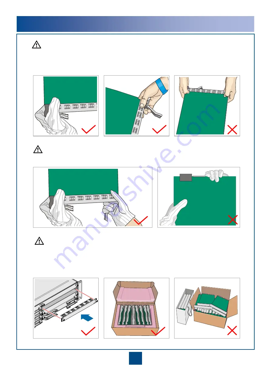
Do not hold a board without hand protection. Wear an ESD wrist strip or ESD gloves before handling a board. 

Insert filler panels into vacant slots on an NE to prevent foreign matters from getting into the NE, which 
may result in faults on the NE.
Boards are fragile and valuable. When handling or placing a board, exercise caution and put it into a 
dedicated packing box.

Holding a board without hand protection

Wearing ESD gloves

Wearing an ESD strip

Hold the front panel of a board with hands. 

Instructions and Precautions for Handling Boards

CAUTION

CAUTION

CAUTION

Summary of Contents for V100R010

Page 1: ...HUAWEI TECHNOLOGIES CO LTD OptiX RTN 950A Radio Transmission System V100R010 IDU Quick Installation Guide Indoor Issue 01 Date 2017 05 30 ...

Page 2: ...ective holders Notice The purchased products services and features are stipulated by the contract made between Huawei and the customer All or part of the products services and features described in this document may not be within the purchase scope or the usage scope Unless otherwise specified in the contract all statements information and recommendations in this document are provided AS IS withou...

Page 3: ...ables Page 23 Installing E1 Cables Pages 21 to 22 Installing IF Jumpers Page 24 Installing XPIC Cables Page 23 Installing STM 1e Cables Page 26 Installing Fibers Pages 25 to 26 Installing Orderwire Phone Cables Page 27 Installing NM Cables Pages 26 to 27 Installing Asynchronous and Synchronous Data Cables Page 29 Installing External Clock Cables Page 28 Cable Layout Effectiveness Page 31 Installin...

Page 4: ...by Using the USB Flash Drive Page 36 Configuring the NE Data by Using the Web LCT Hand Held Tool Page 37 Aligning the Antennas Pages 38 to 40 Checking the Radio Link Status Page 40 Aligning the Dual Polarized Antennas Pages 39 to 40 Aligning the Single Polarized Antennas Pages 38 to 39 End ...

Page 5: ... exceed 250 mm The distance cannot exceed 200 mm for user cables Binding intervals between cable ties for all cables and corrugated pipes outside the cabinet are determined according to the distance between the two horizontal beams If the cable trough does not contain any beams the binding intervals between cable ties cannot exceed 250 mm Pre installation Check Check the telecommunications room ca...

Page 6: ...rs from getting into the NE which may result in faults on the NE Boards are fragile and valuable When handling or placing a board exercise caution and put it into a dedicated packing box Holding a board without hand protection Wearing ESD gloves Wearing an ESD strip Hold the front panel of a board with hands Instructions and Precautions for Handling Boards CAUTION CAUTION CAUTION ...

Page 7: ...autions for Handling Power Cable Terminals Do not pick up the tail end of the red latch by using a finger or a screwdriver to avoid damage Press the front of the red latch Properly move the red latch outwards 2 2 1 1 CAUTION ...

Page 8: ...n and description of the toggle lever switch I ON O OFF Turning on the switch Turning off the switch Pull the switch out gently Turn the switch Release the switch Pull the switch out gently Turn the switch Release the switch 1 1 2 2 3 3 1 1 2 2 3 3 CAUTION A dual channel IF board does not have a toggle lever switch NOTE ...

Page 9: ...e ODU is powered on Connect or disconnect an IF cable only after powering off the ODU Do not connect or disconnect an IF cable when the ODU is powered on Power off the ODU Connect or disconnect the IF cable CAUTION CAUTION CAUTION 2 1 Precautions for Handling IDU side IF Cables Single Channel IF Board Precautions for Handling ODU side IF Cables Single Channel IF Board ...

Page 10: ...d of the cable to the ODU and then connect the other end of the cable to the IDU Connect the IF cable to the ODU Connect the IF cable to the IDU CAUTION When removing or replacing an IF cable disconnect one end of the cable from the IDU and then disconnect the other end of the cable from the ODU Disconnect the IF cable from the IDU Disconnect the IF cable from the ODU ...

Page 11: ...insert the IF board Precautions for Handling IF Boards Remove or insert an IF board only after powering off the ODU Insert the IF board Do not remove or insert an IF board when the ODU is powered on CAUTION CAUTION 3 2 1 3 Skip this step if a dual channel IF board is concerned ...

Page 12: ...ol Socket wrench Torque wrench Hex key Wire clippers Wire stripper RJ45 crimping tool Diagonal pliers Cold press pliers Needle nose pliers Combination pliers Bayonet wrench Utility knife Claw hammer Hammer drill Marker Ladder Soldering iron ESD gloves Heat gun Multimeter ESD gloves Binding strap Insulation tape ESD wrist strap Impact tool File Vacuum cleaner ...

Page 13: ...itions shown in the figure Holes for installation in the N63E 19 inch cabinet Before installing the chassis in the ETSI cabinet adjust the holes for installing mounting ears based on the type of the cabinet Holes for installation in the T63 T66 N66T cabinet NE concatenation port NOTE NOTE 10 11 STM 1 service port ESD port External clock port External time port 1 Bypass E1 port XPIC input output po...

Page 14: ...Store the removed screws properly for installing PGND cables When tightening floating nuts ensure a minimum of 25 mm space on the left and right sides of the RTN 950A for ventilation Floating nut Fixing Floating Nuts a Removing Screws b Installing the RTN 950A NOTE NOTE ...

Page 15: ...screws Installing Mounting Ears a b 2Installing the Chassis in the ETSI Cabinet Fixing Floating Nuts Mounting ears When tightening floating nuts ensure a minimum of 25 mm space on the left and right sides of the IDU for ventilation 2 0 0 2 N M M6 1 4 0 14 N M M4 3 0 0 3 N M M6 Floating nut Installation hole To the ground point on the column of the cabinet or the indoor ground bar Install the cable...

Page 16: ...Installing Mounting Ears b 3Installing the Chassis in the 23 Inch Cabinet 1 4 0 14 N M M4 To the ground point on the column of the cabinet or the indoor ground bar Install the cable tray if provided NOTE 2 0 0 2 N M M6 cable tray 3 0 0 3 N M M6 Store the removed screws properly for installing 23 inch mounting ears NOTE 23 inch mounting ears ...

Page 17: ...ark the positions of the holes for installing mounting ears Drill the holes in the marked positions and install the bolts After the installation ensure a minimum of 50 mm space on the upper and lower sides of the IDU for ventilation 300 mm 1 4 0 14 N M M4 To the ground point on the column of the cabinet or the indoor ground bar Install the cable tray if provided NOTE 2 0 0 2 N M M6 cable tray ...

Page 18: ...ears to 90 degrees and install them in the direction shown in the figure c Installing Mounting Ears d Installing the Cable Tray Optional e If the cable tray is provided install it according to the illustration in the figure Otherwise go to Step g NOTE NOTE ...

Page 19: ...ranging from 52 mm to 60 mm Place the equipment on the wall and then mark the positions of the holes for installing mounting ears Remove the equipment and drill the holes at the marked positions Installing the Chassis on the Wall h Installing PGND Cables i Fan assembly M6x60 expansion bolt Nut Big flat washer Small flat washer PGND cable Mark the hole positions 1 4 0 14 N M M4 NOTE ...

Page 20: ...he ventilation holes on the two sides of the cabinet to avoid impacts on heat dissipation Plastic foot PGND cable Connect PGND cables by using the removed screws 1Fixing Floating Nuts Optional Installing the E1 Panel Remove mounting ears and install plastic feet 1 4 0 14 N M M4 Floating nut Installation hole NOTE ...

Page 21: ...18 2Fixing the E1 Panel 3Installing PGND Cables on the E1 Panel To the ground point on the column of the cabinet or the indoor ground bar ...

Page 22: ...ets for IF Jumpers 1Installing IF Connectors Installing 12 IF Connectors a Installing Two IF Connectors b 1 2 Transfer brackets for two IF jumpers can be installed on walls but cannot be installed in 19 inch cabinets and ETSI cabinets NOTE ...

Page 23: ... in the Cabinet Installing Mounting Ears Installing the Transfer Bracket in the Cabinet 2Installing Transfer Brackets for IF Jumpers Installing Transfer Brackets for IF Jumpers in 19 inch Cabinets a Installing Transfer Brackets for IF Jumpers in ETSI Cabinets b ...

Page 24: ... the Transfer Bracket on the Wall Installing Transfer Brackets for 12 IF Jumpers Method 1 Method 2 Nut Small flat washer Big flat washer M6x60 expansion bolt Tapping screw When installing transfer brackets for two IF jumpers use the method of installing transfer brackets for 12 IF jumpers NOTE ...

Page 25: ...ghten the screws on the panel Before installing and removing inserting a board wear an ESD wrist strap or ESD gloves Before you insert a board ensure that the slot is correct If it is difficult to insert the board stop the operation When installing a PGND cable in the ETSI cabinet connect the PGND cable to the ground point on the left side of the chassis When installing a PGND cable in the 19 inch...

Page 26: ... is 48 V and the total power consumption of the IDU is less than or equal to 420 W the fuse capacity can be set to 15 A NOTE Insert the power cables into the DC connector based on the pin assignment You do not need to prepare the power cables on site if they were prepared before delivery After fastening a cable check whether the cable core is exposed outside the power cable connector terminal If t...

Page 27: ...ds provide the E1 port For information about the pin assignment of an E1 cable see the related table delivered with these E1 cables or the cable part in the Hardware Description For a 1 6 mm diameter E1 cable use a type 75 1 1 connector and a 2 5 mm or 1 7 mm COAX crimping tool when assembling the DDF side connector of the E1 cable 0 4 0 03 N M M2 5 Optional Connecting E1 Cables to the External Eq...

Page 28: ...al Connecting E1 Cables to the TCU6 Board c The TCU6 board which performs conversion between DB44 ports and RJ45 ports of 6xE1 services is generally used with the SP3S 120 ohms board By using Anea96 DB44 E1 cables the TCU6 board can perform conversion between Anea96 ports and RJ45 ports NOTE ...

Page 29: ...E The ISX2 ISM6 and ISV3 XPIC function enabled boards support the XPIC function The IN port on one XPIC IF board must be connected to the OUT port on the other XPIC IF board NOTE If the XPIC function is disenabled on an ISX2 board use a short XPIC cable to connect the IN and OUT ports on the board Otherwise board performance will be affected If the XPIC function is disenabled on an ISV3 board do n...

Page 30: ...ODU must be connected to the IF jumper of the active IF board and the IF cable of the standby ODU must be connected to the IF jumper of the standby IF board If the XPIC IF board is used the IF cable connected to the vertically polarized ODU must be connected to the IF jumper on the IF board that processes vertically polarized waves and the IF cable connected to the horizontally polarized ODU must ...

Page 31: ...al Connecting the IF Jumper to the IF Cable Using a Transfer Bracket c 28 Installation Effectiveness in the 19 Inch Cabinet Installation Effectiveness in the ETSI Cabinet IF jumper IF cable IF jumper IF cable ...

Page 32: ...fectiveness on the Wall Installation Effectiveness of Wall Mounted Transfer Brackets for 12 IF Jumpers Installation Effectiveness of Wall Mounted Transfer Brackets for Two IF Jumpers IF jumper IF cable IF jumper IF cable ...

Page 33: ... For a closed corrugated pipe take protective measures and then route fibers into through corrugated pipe For an open corrugated pipe route fibers through the corrugated pipe and then take protective measures After routing fibers through a corrugated pipe wrap PVC insulation tapes around the cuts of the corrugated pipe Do not feed a large number of fibers in a corrugated pipe It is recommended tha...

Page 34: ...Gateway NE a NMS NMS COM port The CSHO board provides the NMS COM port Installing Fibers b SL1DA board 8Installing STM 1e Cables SL1DA board The CQ1 and SL1DA boards provide the STM 1e electrical port CSHO CQ1 SL1DA EG4 EG4P and EMS6 boards provide optical ports ...

Page 35: ...r cable or a straight through cable on site Ensure that the interconnected network cables do not form a loop and the standby CSH CSTA board is not connected to another network cable NOTE NMS COM EXT NMS 10 Installing Orderwire Phone Cables PHONE port The AUX board provides the PHONE port ...

Page 36: ...ange White Green Green Blue White Blue White Brown Brown 1 2 3 6 4 5 7 8 Twisted pair Twisted pair Positive transmit end of the external clock Negative transmit end of the external clock Negative receive end of the external clock Twisted pair Positive receive end of the external clock Twisted pair External time 1_P External time 1_N External time 2_N External time 2_P The CSHO board provides the C...

Page 37: ... Twisted pair Receives synchronous data signals RING Transmits synchronous data signals TIP Transmits synchronous data signals RING Grounding Receives asynchronous data signals Transmits asynchronous data signals Twisted pair Grounding Assembling Asynchronous and Synchronous Data Cables Based on the Pin Assignment a Twisted pair Installing Synchronous and Asynchronous Data Cables for the IDU b F1 ...

Page 38: ...ted pair External alarm signal input 3 Grounding External alarm signal input 2 External alarm signal input 1 Twisted pair Grounding Twisted pair Grounding Grounding External alarm signal input 4 Positive alarm signal output 1 Negative alarm signal output 1 Positive alarm signal output 2 Negative alarm signal output 2 Positive alarm signal output 1 Negative alarm signal output 1 Positive alarm sign...

Page 39: ...out Effectiveness Power Cables E1 Cables PGND Cables NM Cables IF Jumpers Fibers Ethernet Service Cables This section uses the common cables as examples For the connections of other cables see the previous sections NOTE 1 3 4 7 2 5 5 6 ...

Page 40: ...dy on and green The fan is functioning properly Steady on and red The fan is malfunctioning Off The fan is not powered off Verify that the STAT indicators on the system control switching and timing board are on in green color Before powering on the equipment ensure that the installation of the ODU is completed and the ODU switch on the IF board is set to the OFF state CAUTION FAN PWRA PWRB ...

Page 41: ...USB flash drive For the functions working principles and types of USB flash drives supported see the IDU Hardware Description For a description of the indicators on the USB flash drive see the Commissioning Guide Normally after data is loaded from the USB flash drive to the OptiX RTN 950A the USB port status indicator should be on green USB port status indicator ...

Page 42: ... by Using the Web LCT Configuring NE Data by Using the Hand Held Tool Connect the hand held terminal to the NMS COM port on the active system control cross connect and timing board You can use the hand held tool to configure NE data including basic data of the NE IF ODU information of the radio link parameters for the IF ports parameters for the ODU ports and DCN parameters CSHO board CSHO board N...

Page 43: ...ocal end rotate the antenna widely in the horizontal direction If three signal peaks are tracked adjust the azimuth of the antenna so that the received signal level RSL reaches the peak value at position 2 If two signal peaks are tracked adjust the azimuth of the antenna to the middle of positions 4 and 5 Then adjust the elevation of the antenna so that the three signal peaks such as the signals o...

Page 44: ...ation and azimuth until the RSL reaches the peak within the tracked range Repeat Steps 3 to 4 to ensure that three signal peaks are tracked in both horizontal and vertical directions When the local RSL reaches the maximum peak value tighten the local antenna Adjust the remote antenna to ensure that the RSL at the local end and the RSL at the remote end reach the peak value Check the status of the ...

Page 45: ...ertically polarized signals are aligned with the antennas Refer to Steps 3 and 4 to ensure that the calculated XPD2 XPD2 P3 P4 is equal to or more than 24 dB Record the current angle D2 of the feed boom Repeat Steps 1 to 6 to adjust the feed boom gently ranging from D1 to D2 and ensure that XPD1 and XPD2 are equal to or more than 24 dB Tighten all the screws of the antennas after the alignment is ...

Page 46: ...es are placed tidily and are not cross connected If a cable ladder is used the cables are bound onto the ladder beam tidily If the cable tray is 0 8 m or more higher than the cabinet top a cable ladder is available on the cabinet top to support the cables and to ease stress 11 Cable turns are smooth and have a great bending radius 12 Cable labels are filled in correctly and attached securely They ...

Page 47: ...ference 1 Peeling length reference plane Use a pair of diagonal pliers to trim off one end of a 48 V power cable Place the cable on the peeling length reference plane and use a utility knife to make a mark on the cable according to the 1 1 peeling indicator 2 12 mm 1 1 peeling indicator 12 mm 3 Peel the cable using the diagonal pliers 12 mm Cable core 4 Repeat steps 1 3 to peel a 0 V ground cable ...

Page 48: ...e power cable connector terminal If the cable core is exposed re route the cable into the power cable connector If the cable core is still exposed after you re route the cable peel the cable again After the power switch is turned on sparks may be generated at the exposed cable core when an inappropriate operation is performed Caution Pull the cable slightly Slide the power cable connector s cover ...

Page 49: ...HUAWEI TECHNOLOGIES CO LTD Huawei Industrial Base Bantian Longgang Shenzhen 518129 People s Republic of China www huawei com ...

Reviews: