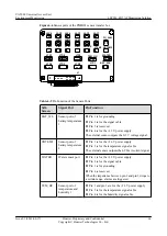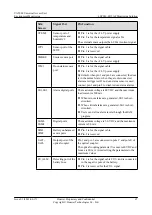
Silk
Screen
Signal Port
Pin Function
JTD1-JTD7 Input ports of the
standby Boolean
value
l
Pin 1 is for the +24 V power supply.
l
Pin 2 is for the +12 V power supply.
l
Pin 3 is for the signal cable.
l
Pin 4 is for grounding.
According to the actual requirements, access related
passive digital signals to pins 2 and pin 3.
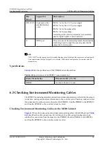
J1
DB50 port
The port connects the monitoring transfer board and the
monitoring board to input the sensor signals and the
output the control signals.
NOTE
"JTD1-JTD7" are the input ports of the standby Boolean value. By default, the sensors are not configured.
You can determine the type of signal to be accessed. With related configuration, the monitor unit can
monitor them.
Specifications
lists the specifications of the PMIB01 sensor transfer box.
Table 6-10
Specifications of the PMIB01 sensor transfer box
Sensor Transfer Box
Dimensions (W x D x H)
PMIB01
140 mm x 96 mm x 31 mm
6.3 Checking Environment Monitoring Cables
The EPMU03 monitoring module monitors the environment parameters collected by the sensors
in real time, and reports the alarm information to the control system. Therefore, make sure that
the connections from the sensors to the ports of the PMIB01, from the PMIB01 to the EPMU03,
and from the EPMU03 to the control system are correct.
Checking Environment Monitoring Cables in the M200 Cabinet
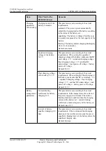
shows the connections of environment monitoring cables in the M200 cabinet.
describes the cable connections. By referring to the cable connection diagram, check
whether the connections from the sensors to the PMIB01, from the PMIB01 to the EPMU03,
and from the EPMU03 to the control system are correct.
UA5000 Universal Access Unit
Environment Monitoring
6 EPS30-4815AF Monitoring Solution
Issue 01 (2012-08-17)
Huawei Proprietary and Confidential
Copyright © Huawei Technologies Co., Ltd.
68


