background image

TP48200A-D17B3 
Troubleshooting Guide 

4 Troubleshooting 


Issue 03 (2013-05-06) 

Huawei Proprietary and Confidential           

Copyright © Huawei Technologies Co., Ltd 

21 


Figure 4-1


Viewing alarm information 


4.2 Common Troubleshooting Procedure 

Step 1


Identify faults based on LED states. 

Step 2


Query fault information by accessing each PMU. 

Step 3


Record the LED states and all fault information displayed on the PMUs. 

Step 4


Determine the fault sources: the DC, AC, PSU, storage battery, or the monitoring unit. 

Step 5


Analyze fault causes based on fault sources by referring to maintenance cases or maintenance 
checklists. 

Step 6


Rectify the faults. 

Step 7


Record the troubleshooting procedure and obtained data. 

Step 8


Query the fault information again to ensure that all faults are rectified. 

Step 9


Record the troubleshooting results. 

Summary of Contents for TP48200A-D17B3

Page 1: ...TP48200A D17B3 V100R001 Troubleshooting Guide Issue 03 Date 2013 05 06 HUAWEI TECHNOLOGIES CO LTD ...

Page 2: ...i and the customer All or part of the products services and features described in this document may not be within the purchase scope or the usage scope Unless otherwise specified in the contract all statements information and recommendations in this document are provided AS IS without warranties guarantees or representations of any kind either express or implied The information in this document is...

Page 3: ...entions The symbols that may be found in this document are defined as follows Symbol Description Alerts you to a high risk hazard that could if not avoided result in serious injury or death Alerts you to a medium or low risk hazard that could if not avoided result in moderate or minor injury Alerts you to a potentially hazardous situation that could if not avoided result in equipment damage data l...

Page 4: ...anges between document issues are cumulative The latest document issue contains all the changes made in earlier issues Issue 03 2013 05 06 Optimized the content of the document including standardizing the terminology and improving the accuracy of the description Issue 02 2012 12 03 Port description is modified Issue 01 2011 03 28 This issue is the first official release ...

Page 5: ...ty 2 1 7 Battery Operation Safety 4 1 8 Hoisting Heavy Objects 5 1 9 Using Ladders 6 1 10 Moving Heavy Objects 7 1 11 Handling Fans 7 1 12 Laying Cables 8 2 TP48200A D17B3 Overview 9 2 1 Typical Networking 9 2 2 Physical Structure 9 2 3 Monitoring Unit 11 2 3 1 Appearance 11 2 3 2 Components 11 2 4 PMU 11 2 5 UIM 02A 13 2 6 Network Diagrams 14 2 7 AC Detection Board 15 2 8 PSU 16 3 Preparations 18...

Page 6: ... Door Control Alarm 26 4 3 13 Smoke Alarm 26 4 3 14 Module Fault 27 4 3 15 Module Shutdown and Protection 27 4 3 16 Communication Failure Between Modules 27 4 3 17 D G Fault 28 4 3 18 Load Fuse Disconnection 28 4 4 Rectifying Other Common Faults 29 4 4 1 The Cabinet Noise Is Too Loud 29 4 4 2 The Fan Stops Rotating 29 4 4 3 The Cabinet Is Immersed in Water 30 4 4 4 The Cabinet Door Cannot Be Opene...

Page 7: ...cument Huawei will not be liable for any consequences caused by the violation of the safety operation regulations and design production and usage standards The safety precautions described in this section are also applicable to other Huawei equipment 1 2 Local Safety Regulations When operating Huawei equipment you must follow the local laws and regulations The safety instructions in this document ...

Page 8: ...on while the device is operating Tighten the thumbscrews using a tool after initial installation and subsequent access to the panel After the installation remove the packing materials from the equipment area 1 6 Electrical Safety High Voltage The high voltage power supply provides power for the device operation Direct or indirect contact through damp objects with high voltage and AC mains supply m...

Page 9: ...ting a power cable verify that the label on the power cable is correct Fuse To ensure that the system runs safely if a fuse is to be replaced the new fuse must be of the same type and specifications Electrostatic Discharge The static electricity generated by human bodies may damage the electrostatic sensitive components on boards for example the large scale integrated LSI circuits Human body movem...

Page 10: ... cause short circuit of circuit boards Storage batteries are high powered and short circuits caused by incorrect operation can result in serious injury Use special insulation tools Switch off the power supply during installation and maintenance Battery short circuit may cause human injuries Although the voltage of ordinary batteries is low the instantaneous high current caused by the short circuit...

Page 11: ...torage battery ensure that its electrodes are upward Leaning or reversing the storage battery is prohibited If your body comes in contact with battery acid wash with clean water immediately and call a doctor if the situation is serious 1 8 Hoisting Heavy Objects Do not walk below the cantilever or hoisted objects when heavy objects are being hoisted Only trained and qualified personnel can perform...

Page 12: ...ith an angle square or your arms as shown in Figure 1 3 When using a ladder ensure that the wider feet of the ladder are downward or take protection measures for the ladder feet to prevent the ladder from sliding Ensure that the ladder is placed securely Ensure that the center of gravity of your body does not deviate from the edges of the two long sides To minimize the risk of falling hold your ba...

Page 13: ...s are required to move a chassis When lifting keep your back straight and move smoothly to avoid injury Move or lift the chassis by holding its lower edge Do not hold the handles on certain modules such as power supply fans and boards because they cannot support the weight of the device 1 11 Handling Fans When handling fans note the following When replacing a component place the component screw an...

Page 14: ... than 0 C 32 F Before laying cables which have been stored in a temperature lower than 0 C 32 F move the cables to an environment of the ambient temperature and store them at the ambient temperature for at least 24 hours Handle cables with caution especially at a low temperature Do not drop the cables directly from the vehicle Trunk cables must be bound separately from strong current cables and hi...

Page 15: ...onfidential Copyright Huawei Technologies Co Ltd 9 2 TP48200A D17B3 Overview 2 1 Typical Networking Figure 2 1 shows the positioning of the TP48200A D17B3 in the typical site power solution Figure 2 1 TP48200A D17B3 in the typical site power solution 2 2 Physical Structure Figure 2 2 shows the TP48200A D17B3 ...

Page 16: ... 06 Huawei Proprietary and Confidential Copyright Huawei Technologies Co Ltd 10 Figure 2 2 TP48200A D17B3 1 Door 2 Base 3 Storage batteries 4 Space for customer equipment 5 AC PDU 6 DC PDU 7 PSU 8 Monitoring unit 9 Fan frame 10 Air filter 11 Heater 12 Cable outlet modules 13 Lamp ...

Page 17: ...f the subrack and is used to connect the PMU and UIM 02A It provides two 96 pin connectors to connect the UIM 02A and a board if required for function extension A 125 pin connector is also provided to connect the PMU PMU The PMU which is hot swappable and serves as the major processing unit performs the monitoring function The PMU connects to the signal transfer board through a 125 pin connector T...

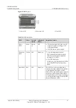
Page 18: ...d is the PMU 02B while the PMU configured with the SNMP daughter board is the PMU 02C Only the PMU 02C supports out of band monitoring All ports in this manual are protected by a security mechanism Figure 2 4 PMU 02B 1 RUN LED 2 ALM LED 3 LCD 4 Buttons 5 COM port 6 COM 485 232 port Figure 2 5 PMU 02C 1 RUN LED 2 ALM LED 3 LCD 4 Buttons 5 COM port used as an FE port 6 COM 485 232 port Table 2 2 LED...

Page 19: ...ton is pressed within 5 minutes After a menu is displayed the LCD screen becomes dark if no button is pressed within 8 minutes On the standby screen the LCD contrast can be decreased by pressing and Enter simultaneously or be increased by pressing and Enter simultaneously 2 5 UIM 02A The UIM 02A panel provides sensor detection ports Boolean value input ports dry contact outputs and communications ...

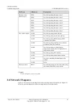
Page 20: ...rms ALM2 Used for reporting door broken alarms ALM3 Used for reporting PSU faults and PSU communication faults ALM4 Used for reporting load fuse blown alarms and battery fuse blown alarms ALM5 Used for reporting over high battery temperature alarms and over high ambient temperature alarms ALM6 Used for reporting TCU alarms ALM7 Used for reporting mains failure alarms ALM8 Used for controlling the ...

Page 21: ...Issue 03 2013 05 06 Huawei Proprietary and Confidential Copyright Huawei Technologies Co Ltd 15 Figure 2 7 Remote management in in band mode Figure 2 8 Remote management in out of band mode 2 7 AC Detection Board The AC detection board detects the AC input voltage ...

Page 22: ...rt Description J1 1 Connects to phase N for detecting the AC input voltage 2 Empty 3 Empty 4 Connects to phase L1 for detecting the AC input voltage J2 Connects to the AC port on the signal transfer board for reporting the AC voltage J3 Empty BAT Empty 2 8 PSU The PSU converts the AC input power into stable 48 V DC power The TP48200A D17B3 can be configured with two three or four PSUs Figure 2 10 ...

Page 23: ...undervoltage The PSU has no power output Protection LED Yellow Off Steady on A prewarning alarm is raised Over temperature shutdown occurs when the environment temperature exceeds 65 C 149 F The PSU hibernates In this case only the protection LED is on and the PSU does not report any alarm Fault LED Red Off Steady on The PSU has no power output due to output overvoltage shutdown fan failure overte...

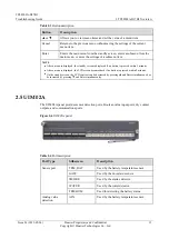
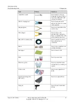
Page 24: ...3 1 Table 3 1 Tool functions Tool Picture Function Multimeter Used to measure the insulation of a cabinet connection of a cable and electric performance specifications of a device such as voltage current and resistance Phillips screwdriver Used to fasten small screws and bolts instead of nuts The Phillips screwdriver has a cross shaped head and provides a small moment of fastening force Flat head ...

Page 25: ... pliers Used to cut insulation tubes and tie wrap Wire stripper Used to remove the insulation layer and jacket from a communication cable with a small cross section Black PVC insulation tape Used to insulate electricity from others wires or conductors Brush Used to clean sundries such as dust and scraps Sand paper Used to remove rust Paint Used to prevent rust Protective gloves Used to protect the...

Page 26: ...rded as a history alarm After you replace the PMU you need to set parameters again For details see the TP48200A D17B3 Quick Installation Guide V100R001_01 The PMU and PSU are hot swappable Take anti static measures when replacing the signal transfer board For example wear an ESD wrist strap Figure 4 1 shows the alarm check method for PMU02B For details about PMU menus see the TP48200A D17B3 Quick ...

Page 27: ...ccessing each PMU Step 3 Record the LED states and all fault information displayed on the PMUs Step 4 Determine the fault sources the DC AC PSU storage battery or the monitoring unit Step 5 Analyze fault causes based on fault sources by referring to maintenance cases or maintenance checklists Step 6 Rectify the faults Step 7 Record the troubleshooting procedure and obtained data Step 8 Query the f...

Page 28: ...pply contact the mains supplier for troubleshooting If the AC input is from the D G check the D G by referring to the diesel generator user manual End 4 3 2 AC Power Off Possible Causes The AC input cable is faulty The mains supply or D G is faulty Solution Step 1 Check that the DC input cable is properly connected Step 2 Check whether there is AC input If there is AC input check whether the AC de...

Page 29: ...oltage or overvoltage threshold is not set properly Solution Step 1 Check that the DC overvoltage or undervoltage alarm threshold is properly set Step 2 When the storage battery supplies power to the load remove all the PSUs and then insert the PSUs one by one Step 3 If an overvoltage alarm is generated after a PSU is inserted the voltage of the PSU exceeds the upper threshold Replace the PSU End ...

Page 30: ...faulty contactor Step 4 Check that the PMU load shutdown voltage is set properly Step 5 Check whether the load power is higher than the configured PSU power If the load power is higher than the configured PSU power add a PSU and set the number of PMUs Ensure that the load power is within the supported range End 4 3 7 Battery Shutdown Possible Causes PMU battery parameters are not set properly The ...

Page 31: ...t is excessively high or low The temperature sensor is faulty Solution Step 1 Check that PMU temperature alarm thresholds are set properly Step 2 Check the temperature control system in the cabinet Repair the faulty temperature control system The alarm is automatically cleared when the temperature in the cabinet is within the specified range Step 3 If the alarm persists check the temperature senso...

Page 32: ...s not exceed the maximum Step 3 Check the charge current If the current is excessively strong switch boost charge to floating charge and check whether the charge current is weakened If the charge current is still excessively strong adjust the current suppression to reduce the charge current Step 4 If the alarm persists replace the faulty battery End 4 3 12 Door Control Alarm Possible Causes The ca...

Page 33: ...tdown and Protection Possible Causes Input overvoltage or undervoltage occurs in the PSU The rectifier module is faulty Solution Step 1 Check whether the mains voltage is greater than the AC overvoltage alarm threshold 300 V of the PSU or smaller than the AC undervoltage alarm threshold 85 V For the power supply network with long time overvoltage or undervoltage negotiate with the maintenance pers...

Page 34: ...Causes The D G signal cable is faulty The PMU is not configured properly The D G is faulty Solution Step 1 Check that the signal cable is properly connected to the D G Step 2 Check that the start permission of the D G in the PMU is set to NO and that the diesel generator is started manually The alarm is cleared after you shut down the D G Step 3 Check the D G by referring to the diesel generator u...

Page 35: ...ce and keep good heat dissipation Step 3 Check that the service board produces power consumption lower than the maximum value Step 4 Replace the faulty fan and then return it to Huawei for repair End 4 4 2 The Fan Stops Rotating Possible Causes The ambient temperature is below the lower threshold for starting a fan If the temperature displayed in the EMS differs from the temperature measured onsit...

Page 36: ...ions where the original tapes are damaged Step 4 Repair the cabinet shell or replace the cabinet Step 5 Use sealing mud to seal all the cable inlets at the base of the cabinet to prevent water intrusion into the cabinet Step 6 Spread the air filter and press it against the vents on the shutter when you clean or replace the air filter End 4 4 4 The Cabinet Door Cannot Be Opened Possible Causes The ...

Page 37: ...termine that a varistor is damaged if its appearance is burnt or broken 5 2 Gas Discharge Tube Check the resistance at both ends of the gas discharge tube In normal cases the resistance is infinitely great If the resistance is very small the gas discharge tube is damaged 5 3 Circuit Breaker The circuit breaker fails typically due to overcurrent or short circuits Check whether the switch of the cir...

Page 38: ...e contactor of the power system is a closed contactor as shown in Figure 5 1 When there is voltage at control poles 1 and 2 but measuring shows that input and output poles 3 and 4 are connected the contactor is faulty Battery branch Open the contactor is in the open state when it is powered off When there is no voltage at the control poles of the contactor check whether the input and output poles ...

Page 39: ...aults occur on the PMU for example breakdown startup failure LCD display failure and keyboard operation failure A fault occurs in the system but the PMU does not generate an alarm The system runs normally false alarm but the PMU generates an alarm Communication interruption occurs when the PMU monitors the subordinate equipment The PMU fails to control and monitor all the modules when these module...

Page 40: ...se AC input at port J1 pin 1 and pin 4 of the board Step 3 Remove the cable connected to port J2 and wrap the connector with ESD tape and then measure the small AC signal sent to the signal transfer board at port J2 pin 1 and pin 5 from the right Step 4 Calculate the AAC small signal The calculation formula is AAC small signal AAC input x 510 400 K For example if the measured AAC input at port J1 ...

Page 41: ...If a load must be disconnected ask for the customer s prior permission The PSU and the PMU are hot swappable For more safety precautions see Safety Information 6 1 Replacing the PSU To replace the PSU perform the following steps Step 1 Loosen the screws on the PSU panel using a flat head screwdriver Step 2 Pull the handle of the PSU outwards and then remove the PSU from the plug in subrack as show...

Page 42: ...circuit breaker to OFF Step 2 Remove the cover plate of the plug in subrack and the protection board using a screwdriver Step 3 Attach labels to the cables connected to the AC detection board and then remove the cables Step 4 Loosen the screws on the AC detection board using a Phillips screwdriver and then remove the AC detection board Step 5 Install and fix the new AC detection board Step 6 Conne...

Page 43: ...eaker using a flat head screwdriver Then remove the circuit breaker as shown in Figure 6 3 Step 4 Press the contact plate at the bottom of the circuit breaker using a flat head screwdriver again to install the new circuit breaker in the correct position Then push the contact plate upwards using the screwdriver Step 5 Install the cables or copper bars to the circuit breaker using a Phillips screwdr...

Page 44: ...B3 Troubleshooting Guide A PMU Menus Issue 03 2013 05 06 Huawei Proprietary and Confidential Copyright Huawei Technologies Co Ltd 38 A PMU Menus This appendix lists the menu trees of the PMU Figure A 1 Menu tree 1 ...

Page 45: ...TP48200A D17B3 Troubleshooting Guide A PMU Menus Issue 03 2013 05 06 Huawei Proprietary and Confidential Copyright Huawei Technologies Co Ltd 39 Figure A 2 Menu tree 2 ...

Page 46: ...TP48200A D17B3 Troubleshooting Guide A PMU Menus Issue 03 2013 05 06 Huawei Proprietary and Confidential Copyright Huawei Technologies Co Ltd 40 Figure A 3 Menu tree 3 ...

Page 47: ...automatic transfer switch B BSC base station controller BLVD battery low voltage disconnection D DDF digital distribution frame E EMC electromagnetic compatibility EMF electromagnetic field EMS element management system ETS European Telecommunication Standard ETSI European Telecommunication Standard Institute L LLVD load low voltage disconnection I IEC International Electro technical Committee M ...

Page 48: ...tary and Confidential Copyright Huawei Technologies Co Ltd 42 MET main earthling terminal P PSU power supply unit PMU power monitoring unit PDU power distribution unit R RoHS restriction of the use of certain hazardous substances S SNMP Simple Network Management Protocol T TCU temperature control unit ...

Reviews: