background image

TP48200A-HX09A2, TBC300A-TCA2 Outdoor Power 
System 
User Manual 

About This Document 


Issue 02 (2019-02-26) 

Copyright © Huawei Technologies Co., Ltd. 

ii 


About This Document 

Purpose 

This document describes the DC power systems in terms of their features, configurations, 
components, and maintenance methods. 

The figures provided in this document are for reference only. 

Intended Audience 

This document is intended for: 


Sales engineers 


Technical support personnel 


Maintenance personnel 
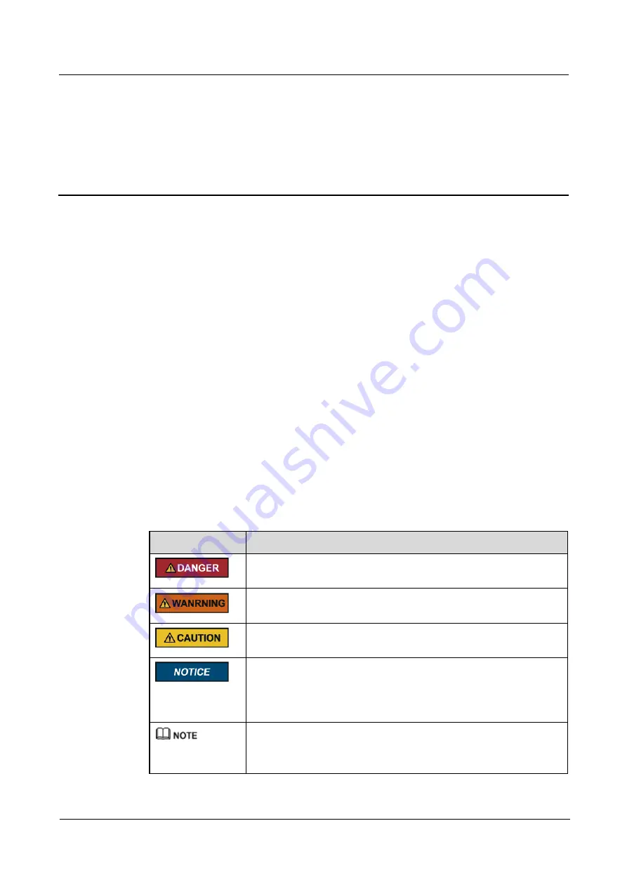
Symbol Conventions 

The symbols that may be found in this document are defined as follows. 

Symbol 

Description 


Indicates an imminently hazardous situation which, if not avoided, 
will result in death or serious injury. 


Indicates a potentially hazardous situation which, if not avoided, 
could result in death or serious injury. 


Indicates a potentially hazardous situation which, if not avoided, may 
result in minor or moderate injury. 


Indicates a potentially hazardous situation which, if not avoided, 
could result in equipment damage, data loss, performance 
deterioration, or unanticipated results. 

NOTICE is used to address practices not related to personal injury. 


Calls attention to important information, best practices and tips. 

NOTE is used to address information not related to personal injury, 
equipment damage, and environment deterioration. 


Summary of Contents for TBC300A-TCA2

Page 1: ...TP48200A HX09A2 TBC300A TCA2 Outdoor Power System User Manual Issue 02 Date 2019 02 26 HUAWEI TECHNOLOGIES CO LTD ...

Page 2: ...stomer All or part of the products services and features described in this document may not be within the purchase scope or the usage scope Unless otherwise specified in the contract all statements information and recommendations in this document are provided AS IS without warranties guarantees or representations of any kind either express or implied The information in this document is subject to ...

Page 3: ...as follows Symbol Description Indicates an imminently hazardous situation which if not avoided will result in death or serious injury Indicates a potentially hazardous situation which if not avoided could result in death or serious injury Indicates a potentially hazardous situation which if not avoided may result in minor or moderate injury Indicates a potentially hazardous situation which if not ...

Page 4: ... 26 Copyright Huawei Technologies Co Ltd iii Change History Changes between document issues are cumulative The latest document issue contains all the changes made in earlier issues Issue 02 2019 02 26 Optimized the content of the document Issue 01 2013 10 24 This issue is the first official release ...

Page 5: ...ier 13 2 4 SMU02B 15 2 5 UIM02C 19 2 6 Temperature Control Unit for the TP48200A HX09A2 22 2 6 1 Heat Exchange 22 2 7 Temperature Control Unit for the TBC300A TCA2 23 2 7 1 TEC 23 2 8 Sensors and Lamp 26 2 8 1 Smoke Sensor 28 2 8 2 Temperature and Humidity Sensor 29 2 8 3 Water Sensor 30 2 8 4 Battery Temperature Sensor 30 2 8 5 Optional Light 31 3 Safety 32 3 1 Health and Safety 32 3 1 1 Overview...

Page 6: ...40 3 2 Equipment Safety 40 3 2 1 Electricity Safety 40 3 2 1 1 High Electrical Leakage 40 3 2 2 Electrostatic Discharge 40 3 2 3 Laying Out Cables 40 3 2 4 Rectifier 41 4 Maintenance 42 4 1 Routine Maintenance 42 4 2 Rectifying Common Faults 44 4 2 1 AC Failure 44 4 2 2 AC Over Volt 44 4 2 3 AC Under Volt 44 4 2 4 DC Over Volt 45 4 2 5 DC Under Volt 45 4 2 6 Batt Chg Overcur 46 4 2 7 LLVD Disconne...

Page 7: ...l Fan of the Heat Exchanger 60 4 4 7 Replacing the External Fan for the Heat Exchanger 61 4 4 8 Replacing the Heat Exchanger Core 64 4 4 9 Replacing the TEC control board 66 4 4 10 Replacing the TEC04C 71 4 4 11 Replacing a Door Status Sensor 74 4 4 12 Replacing a Temperature and Humidity Sensor 75 4 4 13 Replacing a Smoke Sensor 76 4 4 14 Replacing a Battery Temperature Sensor 78 4 4 15 Replacing...

Page 8: ... 1 Overview 1 1 Overview The TP48200A HX09A2 is a south type heat exchange power cabinet that supplies power to 48 V DC outdoor communications equipment The TBC300A TCA2 is a thermoelectric cooler TEC battery cabinet that backs up power for communications equipment Figure 1 1 shows a TP48200A HX09A2 Figure 1 2 shows a TBC300A TCA2 ...

Page 9: ...TP48200A HX09A2 TBC300A TCA2 Outdoor Power System User Manual 1 Overview Issue 02 2019 02 26 Copyright Huawei Technologies Co Ltd 2 Figure 1 1 Appearance of the TP48200A HX09A2 ...

Page 10: ...nual 1 Overview Issue 02 2019 02 26 Copyright Huawei Technologies Co Ltd 3 Figure 1 2 Appearance of the TBC300A TCA2 1 2 Model Number Description Figure 1 3 and Figure 1 4 respectively show the model number description of the TP48200A HX09A2 and TBC300A TCA2 ...

Page 11: ...2 port Communication with Huawei NetEco or third party network management systems NMSs over protocols such as the Simple Network Management Protocol SNMP and Hypertext Transfer Protocol Secure HTTPS to enable remote management and unattended working Liquid crystal display LCD for display and operations Web user interface WebUI for display and operations Access through the mobile app for easy deplo...

Page 12: ...working and batteries start to power loads After the AC power resumes rectifiers power DC loads and charge batteries again The SMU monitors the operating status of each component in the power system in real time and performs appropriate intelligent control When detecting a fault the SMU generates an alarm The SMU monitors and regulates the temperature control unit based on the temperature measured...

Page 13: ...attery low voltage disconnection BLVD load low voltage disconnection LLVD and battery branch N A Rectifier A maximum of four R4850G1s or R4850N1s can be configured N A Site monitoring unit SMU One SMU02B N A User interface module UIM One UIM02C N A Sensor Mandatory one battery temperature sensor one door status sensor and one ambient temperature sensor Optional one smoke sensor one ambient tempera...

Page 14: ...ding measures near pollution sources If a site is near a pollution source it is at most 3 7 km away from salt water such as the sea and salt lakes 3 km away from heavy pollution sources such as smelteries coal mines and thermal power plants 2 km away from medium pollution sources such as chemical rubber and galvanization industries and 1 km away from light pollution sources such as packing houses ...

Page 15: ...utdoor Power System User Manual 2 Components Issue 02 2019 02 26 Copyright Huawei Technologies Co Ltd 8 2 Components 2 1 Interior Figure 2 1 shows the interior of the TP48200A HX09A2 Figure 2 2 shows the interior of the TBC300A TCA2 ...

Page 16: ... output circuit breaker 2 Maintenance socket 3 Load circuit breaker 4 AC SPD surge protective device 5 AC input circuit breaker 6 SMU 7 Battery switch behind the cover 8 Space for installing rectifiers 9 Ground bar 10 Space for installing customer equipment 11 Package entry module 12 Internal fan 13 Battery circuit breaker 14 UIM02C 15 RTN busbar 16 Heat exchanger 17 External fan ...

Page 17: ...2 Interior of the TBC300A TCA2 1 Upper cable holes 2 Space for installing batteries 3 Battery rack 4 Package entry module 5 TEC 6 TCUA control box 7 Ground bar 2 2 Power Distribution Unit AC PDU Figure 2 3 and Figure 2 4 show the AC PDU for the TP48200A HX09A2 Figure 2 3 AC input unit 1 AC input circuit 2 AC input terminal 3 AC surge protective ...

Page 18: ...AC Input Circuit Breaker AC Surge Protection Class AC Load Circuit Breaker Maintenance Socket and Its Protection Mode 110 V AC dual live wire One 2 pole 125 A circuit breaker Class B The normal current In is 30 kA and the maximum current Imax is 60 kA One 2 pole 10 A circuit breaker Multi purpose socket and 10 A residual current device RCD NOTE 110 V AC dual live wire input There is a neutral wire...

Page 19: ...et based on Figure 2 5 to enable the maintenance socket to provide an output voltage of 220 V AC Figure 2 5 Exchanging the cable connections between the maintenance socket and the N wiring terminal DC PDU Figure 2 6 shows the DC PDU for the TP48200A HX09A2 Figure 2 6 DC PDU 1 BLVD circuit breakers 2 LLVD circuit breakers 3 Battery circuit breakers Table 2 2 describes the DC PDU configurations for ...

Page 20: ... 32 A circuit breaker and one 1 pole 16 A circuit breaker NOTE Two 16 A BLVD circuit breakers supply power for the TECs in the two battery cabinets If a lamp is configured use one appropriate load circuit breaker for it Battery Switch Figure 2 7 Battery switch 1 Battery switch The battery switch is set to AUTO by default before delivery meaning that the system is under automatic control Open the p...

Page 21: ...rm indicator and a Fault indicator on its front panel Figure 2 9 shows the rectifier panel Figure 2 9 Rectifier panel 1 Run indicator 2 Alarm indicator 3 Fault indicator Indicator Description Table 2 3 Indicator description Indicator Color Status Description Run indicator Green Steady on The rectifier provides output properly Off The rectifier provides no output Alarm Yellow Off No alarm is genera...

Page 22: ... generates an alarm for shutdown due to ambient overtemperature or undertemperature The rectifier protects against AC input overvoltage or undervoltage The rectifier is hibernating Fault indicator Red Off The rectifier is running properly Steady on The rectifier locks out due to output overvoltage The rectifier has no output due to an internal fault Blinking at 4 Hz The rectifier is loading an app...

Page 23: ... Indicators Table 2 4 SMU02B indicator description Name Color Status Description Run indicator Green Off The SMU is faulty or has no DC input Blinking at 0 5 Hz The SMU is running properly and communicating with the host Blinking at 4 Hz The SMU is running properly but is not communicating with the host Minor alarm indicator Yellow Off No minor or warning alarm has been generated Steady on A minor...

Page 24: ... Port You can quickly deploy a site import and export configuration files export running logs and upgrade software by inserting the USB flash drive that is specially used for site deployment into the USB port After installing the Wi Fi module using the USB port you can access a power supply using the mobile phone app or the browser facilitating site deployment Communications Ports Table 2 6 SMU02B...

Page 25: ...e 2 7 Pin definitions for the FE port Pin Signal Description 1 TX Sends data over FE 2 TX 3 RX Receives data over FE 6 RX 4 5 7 and 8 Reserved N A Table 2 8 Pin definitions for the RS485 RS232 port Pin Signal Description 1 TX Sends data over RS485 2 TX 4 RX Receives data over RS485 5 RX 3 RX232 Receives data over RS232 7 TX232 Sends data over RS232 6 PGND Protective grounding 8 Reserved N A ...

Page 26: ...t and one battery temperature input Figure 2 13 UIM02C panel Ports Table 2 9 UIM02C ports Port Type Silk Screen Description Sensor ports TEM HUM Ambient temperature and humidity sensor WATER Water sensor TEMP1 Ambient temperature sensor 1 TEMP2 Ambient temperature sensor 2 GATE Door status sensor SMOKE Smoke sensor BTEMP Battery temperature sensor Dry contact input ports DIN1 NOTE For the associat...

Page 27: ...M communication port description Communication Port Communications Parameter Communications Protocol Function COM port Baud rate 9600 bit s 19 200 bit s 115 200 bit s M S and Modbus protocol Connects to lower level devices such as the battery inspection unit DC air conditioner NOTE The COM port supports the security mechanism Figure 2 14 Pins in the COM port Table 2 11 Pin definitions for the COM ...

Page 28: ...on 4 TX Sends data over RS485 5 TX 6 PGND Connects to the ground 3 7 8 None N A Pins Figure 2 15 shows the pin numbers of the sensor ports Table 2 12 defines the pins Figure 2 15 UIM02C pin numbers Table 2 12 UIM02C pin definitions Silkscreen No Pin Definitions TEM HUM 1 12 V 2 ENV_TEMP 3 12 V 4 ENV_HUM WATER 1 12 V 2 WATER 3 GND 4 Not defined TEMP1 1 GND ...

Page 29: ...Internal circulation hot air in the equipment compartment is drawn by the internal fan into the heat exchanger passes through the heat exchanging core from top to bottom then releases heat to change to cold air and finally returns to the equipment compartment through the internal air exhaust vent under the heat exchanger External circulation natural air outside the equipment compartment is drawn b...

Page 30: ...awei Technologies Co Ltd 23 Figure 2 16 Heat exchange working principles 2 7 Temperature Control Unit for the TBC300A TCA2 2 7 1 TEC The thermoelectric cooler TEC controls temperatures for the battery compartment which consists of the temperature control unit TCUA and TEC04C TEC04C Figure 2 17 shows a TEC04C ...

Page 31: ...Components Issue 02 2019 02 26 Copyright Huawei Technologies Co Ltd 24 Figure 2 17 TEC04C 1 External circulating fan 2 External heat sink 3 Semiconductor refrigeration chip 4 Internal heat sink 5 Internal circulating fan TCUA Figure 2 18 shows the ports on the TCUA ...

Page 32: ...rinciples Function Working Principle Refrigeration The TCUA controls the TEC04C to cool the internal circulating air The internal circulating fan draws the air inside the battery compartment into the internal heat sink The internal heat sink cools the air and then returns the cooled air to the battery compartment from the air exhaust vent At meantime the external fan draws the external circulating...

Page 33: ...meantime the external fan draws the external circulating air into the external heat sink to accelerate the airflow The air gives out the heat and returns to the external environment from the air exhaust vent of the external heat sink The air exchange between the internal and external environment is implemented so far Figure 2 19 TEC airflow directions 2 8 Sensors and Lamp Figure 2 20 shows the ins...

Page 34: ...ponents Issue 02 2019 02 26 Copyright Huawei Technologies Co Ltd 27 Figure 2 20 Installation positions of the sensors and lamp 1 Temperature sensor 2 Door status sensor 3 Temperature and humidity sensor 4 Battery temperature sensor 5 Smoke sensor 6 Lamp 7 Water sensor ...

Page 35: ... Power System User Manual 2 Components Issue 02 2019 02 26 Copyright Huawei Technologies Co Ltd 28 2 8 1 Smoke Sensor Figure 2 21 Smoke sensor 1 1 Wiring port 2 Base 3 Indicator Figure 2 22 Smoke sensor 2 1 Wiring port 2 Base 3 Indicator ...

Page 36: ...tdoor Power System User Manual 2 Components Issue 02 2019 02 26 Copyright Huawei Technologies Co Ltd 29 2 8 2 Temperature and Humidity Sensor Figure 2 23 Temperature and humidity sensor 1 Figure 2 24 Temperature and humidity sensor 2 ...

Page 37: ...m User Manual 2 Components Issue 02 2019 02 26 Copyright Huawei Technologies Co Ltd 30 2 8 3 Water Sensor Figure 2 25 Water sensor 2 8 4 Battery Temperature Sensor Figure 2 26 shows a battery temperature sensor Figure 2 26 Battery temperature sensor ...

Page 38: ...TP48200A HX09A2 TBC300A TCA2 Outdoor Power System User Manual 2 Components Issue 02 2019 02 26 Copyright Huawei Technologies Co Ltd 31 2 8 5 Optional Light Figure 2 27 Light ...

Page 39: ...owing the general precautions in this document follow the specific safety instructions given by Huawei Only trained and qualified personnel are allowed to install operate and maintain Huawei equipment This product should be used in the environment that meets design specifications Otherwise the product may be damaged and the resulting product exceptions or component damage are beyond the warranty s...

Page 40: ...system For DC supplied models Reinforced insulation or double insulation must be provided to isolate the DC source from the AC mains supply For DC supplied model The device applies to DC power source that complies with the Safety Extra Low Voltage SELV requirements in IEC 60950 1 based safety standards Prepared conductors are connected to the terminal block and only the appropriate AWG Type of wir...

Page 41: ...The personnel who install the AC facility must be qualified to perform high voltage and AC operations Do not wear conductive articles such as watches hand chains bracelets and rings during the operation When water is found in the rack or the rack is damp switch off the power supply immediately When the operation is performed in a damp environment make sure that the device is dry Non standard and i...

Page 42: ...s environment 3 1 4 Battery 3 1 4 1 Storage Battery Before operating storage batteries carefully read the safety precautions for battery handling and connection Improper handling of storage batteries causes hazards When operating storage batteries avoid short circuit and overflow or leakage of the electrolyte Electrolyte overflow may damage the device It will corrode metal parts and circuit boards...

Page 43: ...valent type recommended by the manufacturer Keep away metal objects which may cause battery short circuit from batteries If metal objects must be used first disconnect the batteries in use before performing any other operations Hazardous Gas Do not use unsealed lead acid storage batteries Lead acid storage batteries must be placed horizontally and stably to prevent the batteries from releasing fla...

Page 44: ...s fulfill the following requirements Only trained personnel can work at heights Prevent the devices and tools that you carry from falling down Take safety and protection measures for example wear a helm and safety belt Wear warm clothes when working at heights in a cold region Before working at heights check that all the lifting facilities are in good condition 3 1 5 1 Hoisting Heavy Objects Do no...

Page 45: ...ing the ladder Placing a Ladder The recommended gradient of ladders is 75 degrees You can measure the gradient of the ladder with a right angle or your arms When using a ladder ensure that the wider feet of the ladder are downward or take protection measures for the ladder feet to prevent the ladder from sliding Ensure that the ladder is placed securely Climbing Up a Ladder When climbing up a ladd...

Page 46: ...ear an eye protector when drilling holes This is to prevent your eyes from being injured by the splashing metal scraps Ensure that the scraps caused by drilling do not enter the cabinet Drilling holes without complying with the requirements affects the electromagnetic shielding performance of the cabinet After drilling clean the metal scraps immediately 3 1 6 2 Sharp Objects Before you hold or car...

Page 47: ...r handling of plastic articles causes static electromagnetic fields on human bodies These static electromagnetic fields cannot be eliminated until the static is discharged To prevent electrostatic sensitive components from being damaged by the static on human bodies you must wear a well grounded electrostatic discharge ESD wrist strap when touching the device or handling boards or application spec...

Page 48: ...26 Copyright Huawei Technologies Co Ltd 41 3 2 4 Rectifier When a rectifier is running the temperature around the air exhaust vent at the rear is high Do not touch the vent or cover the vent with cables or other objects To prevent electric shocks do not put your hands into rectifier slots ...

Page 49: ...d By observing or by locking and unlocking the door The door lock fails Replace the door lock Fan Dust accumulates on the fan surface By observing Thick dust accumulates on the fan surface Clean up the dust from the fan The fan surface is intact and the rotational speed noise and vibration is in the normal range By observing and listening to the fans The fan is damaged the noise is too loud or the...

Page 50: ...per ature alarm happens frequently and the temperature inside the cabinet is much higher than the ambient temperature Dust accumulates on the air filter Replace the air filter Electrical specifications The output voltage is normal Multimeter The battery circuit voltage or load circuit voltage exceeds its threshold For details see 4 2 Rectifying Common Faults Preventive maintenance inspection PMI I...

Page 51: ...the AC input circuit breaker is OFF If so handle the fault which caused the AC input circuit breaker to turn OFF and then switch on the circuit breaker 3 Check whether the AC input voltage is lower than 50 V AC If so handle the power grid fault 4 2 2 AC Over Volt Possible Causes The AC overvoltage alarm threshold is incorrectly set on the SMU The power grid is faulty Measures 1 Check whether the A...

Page 52: ...tifiers one by one and check whether the alarm is cleared If the alarm still exists reinstall the rectifier If the alarm is cleared replace the rectifier 4 2 5 DC Under Volt Possible Causes An AC power failure has occurred The DC undervoltage alarm threshold is incorrectly set on the SMU The system configuration is incorrect The power system voltage has been manually set to a very low value Rectif...

Page 53: ...easures 1 Check whether an AC power failure has occurred If so rectify the fault to restore the AC power supply 2 Check whether loads are manually disconnected If so check with other maintenance personnel whether the loads can be reconnected 3 Check whether the load disconnection voltage 44 V DC by default has been set to a very high value on the SMU If so adjust it to a normal value 4 2 8 BLVD Di...

Page 54: ... the power system that has an ambient temperature sensor installed Possible Causes The high ambient temperature alarm threshold is incorrectly set The temperature control system is faulty in the cabinet where the ambient temperature sensor is located The ambient temperature sensor is faulty Measures 1 Check whether the high ambient temperature alarm threshold 50 C by default is correctly set If no...

Page 55: ...gh humidity alarm threshold 80 RH by default is correctly set If no adjust it to a proper value 2 Check whether water intrudes into the cabinet If yes wipe the water with dry cotton or other tools and rectify the fault 3 Check whether the humidity sensor is faulty If yes replace the humidity sensor 4 2 13 Low Ambient Humidity This alarm is generated only for the power system that has a humidity se...

Page 56: ...wer system that has a battery temperature sensor installed Possible Causes The low battery temperature alarm threshold is incorrectly set on the SMU The battery temperature control system is faulty The battery temperature sensor is faulty Measures 1 Check whether the low battery temperature alarm threshold 10 C by default is correctly set If not set the threshold to the correct value 2 Check wheth...

Page 57: ...that has a smoke sensor installed Possible Causes There is smoke inside the cabinet The smoke sensor is faulty Measures 1 Check whether there is smoke inside the cabinet If so disconnect the power supply from the cabinet handle the fault and then restart the system and clear the alarm on the SMU 2 Check whether the smoke sensor is faulty If the smoke sensor is faulty replace it 4 2 19 Rect Fault P...

Page 58: ...it after the indicator turns off If the alarm persists replace the rectifier 4 2 21 Rect Comm Fault Possible Causes A rectifier has been removed Rectifier connections are loose A rectifier is faulty Measures 1 Check whether a rectifier has been removed If so reinstall it 2 If the rectifier is in position remove the rectifier and reinstall it 3 If the alarm persists replace the rectifier 4 2 22 Loa...

Page 59: ...eaker Faults The following indicate that the circuit breaker is faulty The circuit breaker cannot be switched to ON OFF after the short circuit fault for its end circuit is rectified When the circuit breaker is switched to ON and its input voltage is normal the voltage between the two ends of the circuit breaker exceeds 1 V The input voltage is normal but the resistance between both ends of the ci...

Page 60: ...rectifiers and the communications cables are normal The SMU cannot monitor AC or DC power distribution when communications cables are intact and AC and DC power distribution is normal Parameters cannot be set or running information cannot be viewed on the SMU 4 4 Replacing Components 4 4 1 Replacing a Rectifier Prerequisites You have obtained an ESD wrist strap a pair of protective gloves an ESD b...

Page 61: ... the rectifier into the subrack slowly along the guide rail Then lock the handle Step 6 Tighten the screws on the handle as shown in Figure 4 2 Figure 4 2 Installing a new rectifier Step 7 Take off protective gloves End Follow up Procedure Pack the removed component and return it to Huawei local warehouse 4 4 2 Replacing an SMU Prerequisites The cabinet door key is available The new SMU is intact ...

Page 62: ... the locking latch towards the right Step 5 Reset the parameters on the SMU Figure 4 4 Installing an SMU End Follow up Procedure Pack the removed component and send it to the local Huawei warehouse 4 4 3 Replacing the PCB of UIM02C Prerequisites An ESD wrist strap ESD gloves ESD box or bag cabinet door key and required tools are available The new PCB of UIM02C is intact Procedure Step 1 Connect th...

Page 63: ...nologies Co Ltd 56 Figure 4 5 Taking out the main board of UIM02C Step 4 Remove the 48 V power cable from the PCB of UIM02C Figure 4 6 Removing the 48 V power cable Step 5 Record the positions where the PCB of UIM02C connects to all the cables and then disconnect the cables Step 6 Remove the PCB as shown in Figure 4 7 ...

Page 64: ...ed on the recorded information Step 12 Disconnect the ground cable from the ESD wrist strap and remove the ESD wrist strap and ESD gloves End Follow up Procedure Pack the removed component and return it to the local Huawei warehouse 4 4 4 Replacing an AC SPD Prerequisites An ESD wrist strap ESD gloves ESD box or bag required tools and cabinet door key are available The new AC SPD is intact and the...

Page 65: ... replacing an AC circuit breaker switch off the upstream input circuit breaker The cabinet door key insulation tape and required tools are available The new circuit breaker is intact and has the same specifications as the circuit breaker to be replaced Procedure Step 1 Switch off the circuit breaker that is to be replaced Step 2 Record the positions where the output cable and signal cable terminal...

Page 66: ... Press the buckle at the circuit breaker base using an insulated flat head screwdriver and install the new circuit breaker Then remove the screwdriver so that the buckle secures the circuit breaker to the guide rail Step 7 Tighten the screw that secures the lower port of the circuit breaker Step 8 Remove the insulation tape from the output power cable and signal cable terminals Then connect the ou...

Page 67: ...e AC input Procedure Step 1 Disconnect the 48V power cable from the UIM02C 1 Connect the ground cable to the ESD wrist strap and wear the ESD wrist strap and ESD gloves 2 Record the position where the UIM02C panel connects to the signal cable and then disconnect the signal cable 3 Unscrew the UIM02C panel and take out the UIM02C as shown in Figure 4 5 4 Remove the 48V power cable from the UIM02C a...

Page 68: ...screws Step 7 Connect the wiring terminal for the fan Step 8 Connect the 48V power cable to the UIM02C Step 9 Push in the UIM02C and secure the screws Step 10 Connect the signal cable to the UIM02C panel based on the record made previously Step 11 Disconnect the ground cable from the ESD wrist strap and take off the ESD wrist strap and ESD gloves End 4 4 7 Replacing the External Fan for the Heat E...

Page 69: ... UIM02C 1 Connect the ground cable to the ESD wrist strap and wear the ESD wrist strap and ESD gloves 2 Record the position where the UIM02C panel connects to the signal cable and then disconnect the signal cable 3 Unscrew the UIM02C panel and take out the UIM02C as shown in Figure 4 5 4 Remove the 48V power cable from the UIM02C as shown in Figure 4 6 Step 2 Disconnect the wiring terminal for the...

Page 70: ...ixing plate as shown in Figure 4 15 Figure 4 15 Removing the external fan Step 6 Place the new fan based on the recorded installation direction see the arrow marks on the fan and screw the fan to the fan fixing plate Step 7 Properly place the fan fixing plate and screw up the fan fixing plate Step 8 Properly place the fan baffle and screw up the fan baffle Step 9 Connect the wiring terminal for th...

Page 71: ...u have obtained an ESD wrist strap a pair of ESD gloves a pair of protective gloves the cabinet door key and maintenance tool box Context You do not need to disconnect the AC input for the system Procedure Step 1 Disconnect the 48V power cable from the UIM02C 1 Connect the ground cable to the ESD wrist strap and wear the ESD wrist strap and ESD gloves 2 Record the position where the UIM02C panel c...

Page 72: ...nging core or replace it with a new one Step 5 Install the heat exchanging core Step 6 Take off protective gloves Step 7 Connect the 48V power cable to the UIM02C Step 8 Push in the UIM02C and secure the screws Step 9 Connect the signal cable to the UIM02C panel based on the record made previously Step 10 Disconnect the ground cable from the ESD wrist strap and take off the ESD wrist strap and ESD...

Page 73: ...nect the power cable from the TEC control board but do not need to disconnect the AC input for the system Procedure Step 1 Connect the ground cable to the ESD wrist strap and wear the ESD wrist strap and ESD gloves Step 2 Switch off the circuit breaker for the TEC control box on the DC PDU Step 3 Remove the power cable from the TEC control box Step 4 Record the position where the TEC control board...

Page 74: ...C300A TCA2 Outdoor Power System User Manual 4 Maintenance Issue 02 2019 02 26 Copyright Huawei Technologies Co Ltd 67 Figure 4 17 Removing the TEC control box Step 6 Unscrew the TEC control board as shown in Figure 4 18 ...

Page 75: ...where the cables for the TEC04C connect to the TEC board disconnect the cables and then take down the TEC control board Step 8 Record the information about the jumper caps on the TEC control board Figure 4 19 Jumper caps on the TEC control board Step 9 Set the jumper caps for the new TEC control board based on the recorded information Step 10 Install a new TEC control board into the TEC control bo...

Page 76: ...2 2019 02 26 Copyright Huawei Technologies Co Ltd 69 Figure 4 20 Installing a new TEC control board Step 11 Connect the cable between the TEC04C and the TEC control board based on the recorded information Step 12 Tighten the screws to secure the TEC control box as shown in Figure 4 21 ...

Page 77: ...ect the signal cable to the TEC control box based on the recorded information Step 14 Connect and tighten the power cable to the TEC control box Step 15 Switch on the circuit breaker for the TEC control box on the DC PDU Step 16 Disconnect the ground cable from the ESD wrist strap and take off the ESD wrist strap and ESD gloves End Follow up Procedure Send the replaced TEC board for repair ...

Page 78: ...ol box and record the cable information 1 Connect the ground cable to the ESD wrist strap and wear the ESD wrist strap and ESD gloves 2 Switch off the circuit breaker for the TEC control box on the DC PDU 3 Remove the power cable from the TEC control box 4 Record the position where the TEC control board connects to the signal cable and then disconnect the signal cable 5 Unscrew the TEC control box...

Page 79: ...A2 Outdoor Power System User Manual 4 Maintenance Issue 02 2019 02 26 Copyright Huawei Technologies Co Ltd 72 Figure 4 22 Removing the external cover from the cabinet door 2 Unscrew and remove the TEC04C as shown in Figure 4 23 ...

Page 80: ...le and signal cables of the TEC04C to the TEC control board based on the recorded information 2 Tighten the screws to secure the TEC control box 3 Connect the signal cable to the TEC control box based on the recorded information Step 5 Connect and tighten the power cable to the TEC control box Step 6 Switch on the circuit breaker for the TEC control box on the DC PDU Step 7 Disconnect the ground c...

Page 81: ...positions where the alarm cables connect to the door status sensor and unscrew the alarm cables Step 3 Unscrew the door status sensor as shown in Figure 4 24 Figure 4 24 Removing the door status sensor Step 4 Remove the shell of the new door status sensor and remove the screws from the alarm cables Step 5 Properly place the new door status sensor at the installation position and tighten the screws...

Page 82: ...is intact Procedure Step 1 Connect the ground cable of the ESD wrist strap and wear the ESD wrist strap and ESD gloves Step 2 Remove the temperature and humidity sensor cable from the user interface module UIM as shown in Figure 4 25 Figure 4 25 Removing the temperature and humidity sensor cable Step 3 Remove the temperature and humidity sensor as shown in Figure 4 26 1 Hold down the button on the...

Page 83: ...the recorded information 4 Properly place the upper cover of the sensor and secure it to the base Step 5 Reconnect the temperature and humidity sensor cable to the UIM Step 6 Disconnect the ground cable of the ESD wrist strap and remove the ESD wrist strap and ESD gloves End 4 4 13 Replacing a Smoke Sensor Prerequisites You have obtained an ESD wrist strap a pair of ESD gloves an ESD box or bag th...

Page 84: ...e sensor in the OPEN direction 3 Unscrew the smoke sensor base Figure 4 27 Removing the smoke sensor Step 3 Install a new smoke sensor 1 Properly place the smoke sensor base and tighten the screws for it 2 Properly place the new smoke sensor and press and push it in the CLOSE direction 3 Reconnect the removed cables to the smoke sensor Step 4 Disconnect the ground cable from the ESD wrist strap an...

Page 85: ...s an ESD box or bag the cabinet door key and a maintenance tool kit The new battery temperature sensor is intact Procedure Step 1 Connect the ground cable to the ESD wrist strap and put on the ESD wrist strap and ESD gloves Step 2 Remove the battery temperature sensor cable from the UIM as shown in Figure 4 28 Figure 4 28 Removing the battery temperature sensor cable Step 3 Cut off the cable tie o...

Page 86: ...r cable to the UIM Step 6 Disconnect the ground cable from the ESD wrist strap and take off the ESD wrist strap and ESD gloves End 4 4 15 Replacing a Temperature Sensor Prerequisites You have obtained an ESD wrist strap a pair of ESD gloves an ESD box or bag the cabinet door key and a maintenance tool kit The new temperature sensor is intact Procedure Step 1 Connect the ground cable to the ESD wri...

Page 87: ...the cable tie of the sensor in the equipment compartment and remove it Figure 4 31 Position of the temperature sensor Step 4 Properly place the new temperature sensor in the equipment compartment and bind it securely with a cable tie Step 5 Reconnect the temperature sensor cable to the UIM Step 6 Disconnect the ground cable from the ESD wrist strap and take off the ESD wrist strap and ESD gloves E...

Page 88: ... pair of ESD gloves an ESD box or bag the cabinet door key and a maintenance tool kit The new water sensor is intact Procedure Step 1 Connect the ground cable to the ESD wrist strap and put on the ESD wrist strap and ESD gloves Step 2 Remove the water sensor cable from the UIM as shown in Figure 4 32 Figure 4 32 Removing the water sensor cable Step 3 Cut off the cable tie of the water sensor and r...

Page 89: ...HX09A2 TBC300A TCA2 Outdoor Power System User Manual 4 Maintenance Issue 02 2019 02 26 Copyright Huawei Technologies Co Ltd 82 Figure 4 33 Position of the water sensor in the battery cabinet in stacked scenario ...

Page 90: ...ter sensor in the power cabinet in non stacked scenario Step 4 Properly place the new water sensor and bind it securely with a cable tie ensure that the sensor is 5 mm to 10 mm away from the cabinet bottom Step 5 Reconnect the water sensor cable to the UIM Step 6 Disconnect the ground cable from the ESD wrist strap and take off the ESD wrist strap and ESD gloves End ...

Page 91: ...70 C Operating humidity 5 95 RH non condensing Transportation humidity 5 95 RH non condensing Storage humidity 5 95 RH non condensing Altitude 0 4000 m When the altitude ranges from 2000 m to 4000 m the operating temperature decreases by 1 C for each additional 200 m A 2 Electrical Specifications Table A 2 Electrical specifications Item Specifications AC input AC input system and input voltage 110...

Page 92: ...very threshold When the voltage is restored to 290 V AC the output resumes AC input undervoltage protection threshold 85 V AC AC input undervoltage recovery threshold When the voltage is restored to 90 V AC the output resumes DC output protection DC output overvoltage protection threshold Range 58 5 60 5 V DC If an overvoltage occurs inside a rectifier the rectifier locks out If the external volta...

Page 93: ...port 2 kV criterion B DC power port 2 kV criterion B Radiated susceptibility RS Field strength 10 V m criterion A Conducted susceptibility CS Signal port 3 V criterion A power port 10 V criterion A Surge susceptibility EN61000 4 5 AC and DC power ports differential mode 2 kV criterion B common mode 4 kV criterion B Signal port differential mode 0 5 kV criterion B common mode 1 kV criterion B A 4 C...

Page 94: ...ations Item R4850G1 R4850N1 Efficiency Highest efficiency 96 95 230 V AC 20 to 90 load power Highest efficiency 92 5 91 5 230 V AC 35 to 80 load power Output power 3000 W 176 300 V AC 1200 W 85 175 V AC 2900 W 176 300 V AC 1200 W 85 175 V AC Dimensions H x W x D 88 9 mm x 103 mm x 243 mm 88 9 mm x 103 mm x 243 mm Weight 2 8 kg 2 5 kg A 6 TEC04C Specifications Table A 6 TEC04C specifications Item S...

Page 95: ...Operating voltage 36 V DC to 60 V DC Temperature sensor Detecting range 20 C to 80 C precision 2 C A 7 Lamp Specifications Table A 7 Lamp specifications Item Specifications Rated voltage 48 V DC Operating current 20 mA Power consumption 1 W Light source type Light emitting diode LED Luminosity 300 cd m2 at a distance of 500 mm away from the LED cover Dimensions L x maximum shape diameter 154 mm x ...

Page 96: ...TCA2 Outdoor Power System User Manual B Electrical Conceptual Diagram Issue 02 2019 02 26 Copyright Huawei Technologies Co Ltd 89 B Electrical Conceptual Diagram Figure B 1 Electrical conceptual diagram of the TP48200A HX09A2 ...

Page 97: ...ut 5 DIN6 Dry contact input 6 Dry contact output ALM1 Reports alarms for mains faults Default mode Close alarm Open normal can be modified as required ALM2 Reports alarms for DC output overvoltage or undervoltage Default mode Close alarm Open normal can be modified as required ALM3 Reports alarms for module faults Default mode Close alarm Open normal can be modified as required ALM4 Reports alarms...

Page 98: ...for overhigh or over low battery temperatures Default mode Close alarm Open normal can be modified as required ALM7 Reports battery cabinet alarms for fan faults TEC faults and door open Default mode Close alarm Open normal can be modified as required ALM8 Reports power cabinet fan faults or high temperatures detected by the temperature control unit TCU in the power cabinet Default mode Close alar...

Page 99: ...yms and Abbreviations A AC alternating current ACDB alternating current distribution box B BLVD battery low voltage disconnection C CS conducted susceptibility D DC direct current E EFT electrical fast transient EMC electromagnetic compatibility ESD electrostatic discharge F FE fast ethernet H HAU heater assembly unit HTTPS Hypertext Transfer Protocol Secure ...

Page 100: ...ical Commission IP Internet Protocol L LCD liquid crystal display LLVD load low voltage disconnection M MTBF mean time between failures R RS radiated susceptibility S SMU site monitoring unit SNMP Simple Network Management Protocol SPD surge protective device T TCP Transmission Control Protocol TCUA temperature control unit A THD total harmonic distortion U UIM user interface module ...

Reviews: