2
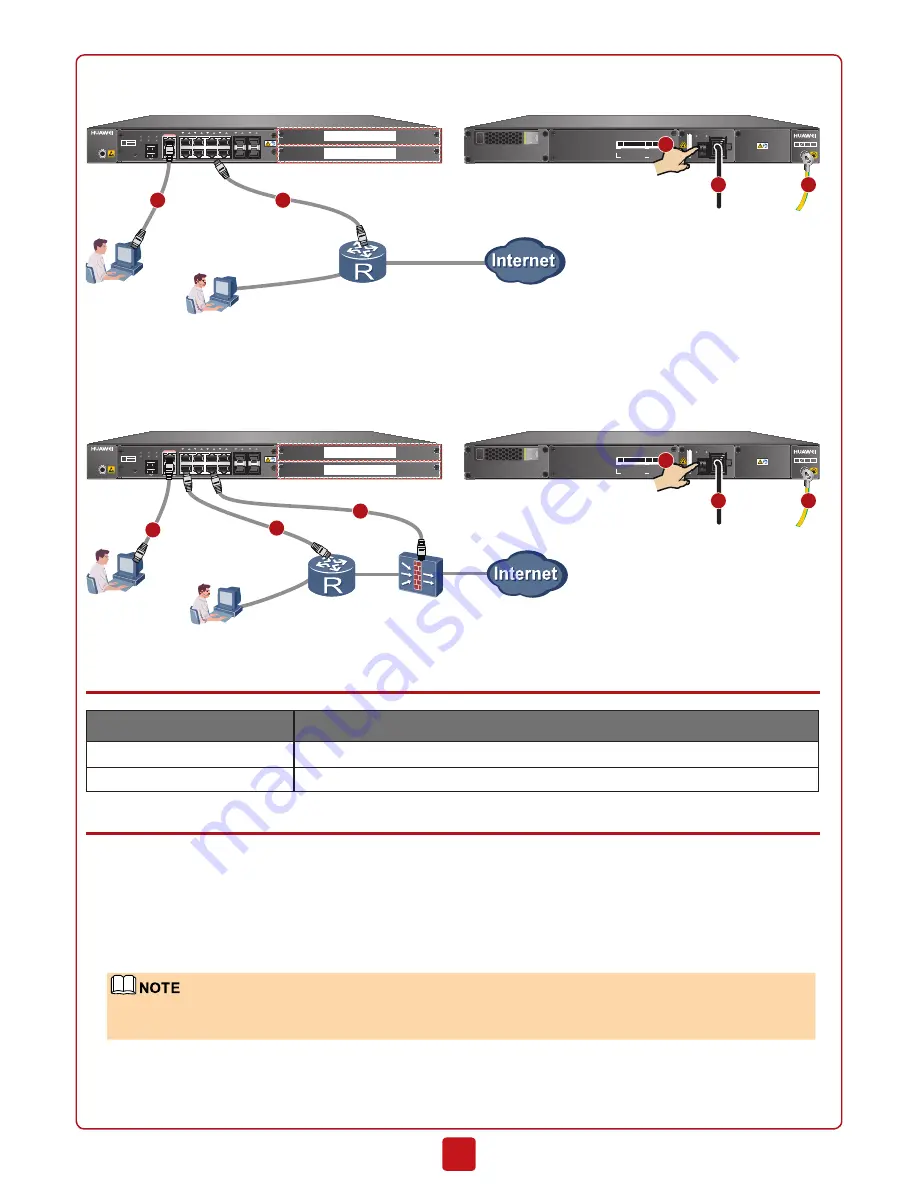
5. Turn on the power switch. When the SYS indicator on the front panel is blinking (once every two seconds), the device is
running and ready for configuration.
SVN5800
4 HDD
5 PWR 6 PWR
INPUT OUTPUT
ON
OFF
~100-240V;50/60Hz;2.5A
XXXXXXXXXXXXXXXXXXXXXXXXXXX
SM-HDD-SAS300G-B
SVN5800
0
1
2
3
4
5
6
7
8
9
10
11
0
1
RST
SYS
ALM
PWR
HDD
MGMT
MODE
0/1
2
3
CONSOLE
MGMT
Front panel
Rear panel
Administrator
WSIC(Slot 3)
WSIC(Slot 2)
5
4
1
Router or Firewall
Intranet
GE1/0/4
2
GE0/0/0
3
•
Two-Armed Mode: Connect one port to the router and another (uses the pre-NAT virtual gateway
address) to the
fi
rewall.
The SVN is connected to both the intranet (router or core switch) and Internet (the
fi
rewall).
SVN5800
4 HDD
5 PWR 6 PWR
INPUT OUTPUT
ON
OFF
~100-240V;50/60Hz;2.5A
XXXXXXXXXXXXXXXXXXXXXXXXXXX
SM-HDD-SAS300G-B
SVN5800
0
1
2
3
4
5
6
7
8
9
10
11
0
1
RST
SYS
ALM
PWR
HDD
MGMT
MODE
0/1
2
3
CONSOLE
MGMT
Front panel
Rear panel
Administrator
GE0/0/0
WSIC(Slot 3)
WSIC(Slot 2)
5
4
1
Intranet
GE1/0/4
2
GE1/0/0
2
3
Default Con
fi
guration
Item
Description
MGMT (management port)
The MGMT port is numbered GE0/0/0 and assigned with IP address 192.168.0.1.
Administrator account/password
You can use the default account/password (admin/Admin@123).
Use the Web con
fi
guration wizard to complete basic network con
fi
guration.
1. Set the IP address to 192.168.0.2 (or any other in the range of 192.168.0.2 to 192.168.0.254) and subnet mask to
255.255.255.0 of the corresponding network interface on the administration PC.
2. Open a web browser and navigate to https://192.168.0.1:8443.
3. Enter the user name (admin) and password (Admin@123) in the login dialog box, and then click
Login
. You need to
change the user password as instructed after the first login.
4. In the
Basic Network Configuration Wizard
page that is displayed, select a networking mode according to your cabling
and click
Next
.
If the
Basic Network Con
fi
guration Wizard
page is not displayed, click the
System
tab and choose
Wizard >
Basic Network Con
fi
guration Wizard
on the left navigation tree.
5. Select and activate the License file and click
Next
. To obtain the License file, refer to
License Application Guide
.
6. Configure the interfaces. In one-armed mode, configure the service interface (GE1/0/4 in the cabling figure); in two-armed
mode, configure the inside interface (GE1/0/0 in the cabling figure) and outside interface (GE1/0/4 in the cabling figure)
and click
Next
.


