background image

10

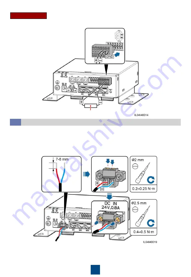
Two-Wire System

PT100/PT1000 temperature sensor

When the PT ports need to be connected to a two-wire PT100/PT1000, use a short-circuit cable to 
short-circuit GND and 

– of the ports.

Connecting the 24 V Input Power Cable

4.10

The 24 V input power cable needs to be connected in the following scenarios:
• The 24 V DC power supply is used.
• The SmartModule connects to the power supply over the 12 V input power port, and the 24 V 

input power port functions as the 12 V output power port to supply power to a device.

Summary of Contents for SmartLogger 3000B

Page 1: ...HUAWEI TECHNOLOGIES CO LTD Issue 04 Part Number 31500BWV Date 2020 05 11 SmartModule1000A01 Quick Guide ...

Page 2: ...and local regulations 1 LED indicators RUN ALM 2 Mounting ear 3 Guide rail clamp 4 COM ports COM1 COM2 COM3 5 DI ports DI 6 12 V output power port 12V GND 7 AI ports AI 8 Potential transformer PT ports PT1 PT2 9 Protective ground point 10 12 V input power port DC IN 12V 1A 11 24 V input power port DC IN 24V 0 8A 12 GE ports GE1 GE2 GE3 GE4 13 RST button RST Before installing the device closely rea...

Page 3: ...en wall mounting the SmartLogger and SmartModule ensure that the cable connection area faces downward for ease of cable connection and maintenance You are advised to use the delivered tapping screws and expansion tubes 1 Connect the SmartLogger to the SmartModule using a connecting plate If the SmartLogger and SmartModule have been combined before delivery skip this step ...

Page 4: ...ide Rail Mounted Installation Stand alone Before installation prepare a standard 35 mm guide rail and secure it The recommended effective length of the guide rail is 360 mm or greater Ensure that the SIM card slot on the SmartLogger is not blocked ...

Page 5: ... the SIM card slot on the SmartLogger is not blocked 1 Connect the SmartLogger to the SmartModule using a connecting plate 2 Install the SmartLogger and SmartModule If the SmartLogger and SmartModule have been combined before delivery you only need to remove the mounting ears and guide rail clamps in the middle You do not need to use a connecting plate to connect the SmartLogger and SmartModule ...

Page 6: ...d cable connection operations see the documents delivered with the PT100 PT1000 Optional 24 V input power cable Two core cable with a cross sectional area of 0 2 1 5 mm2 or 24 16 AWG Connect cables in accordance with the installation laws and regulations of the country or region where the project is located Before connecting cables to ports leave enough slack to reduce the tension on the cables an...

Page 7: ...ors It is recommended that the cable length be less than or equal to 100 m When crimping the network cable ensure that the shielding layer of the cable is securely connected to the metal shell of the RJ45 connectors 1 White and orange 2 Orange 3 White and green 4 Blue 5 White and blue 6 Green 7 White and brown 8 Brown Connecting the 12 V Input Power Cable 4 4 The SmartLogger connects to the power ...

Page 8: ...mmunications devices such as a solar inverter an environmental monitoring instrument EMI and a power meter over the COM port Ensure that the RS485 and RS485 terminals are respectively connected to the COM and COM ports on the SmartModule Cascading Connection You are advised to connect fewer than 30 devices to each RS485 route The baud rate communications protocol and parity mode of all devices on ...

Page 9: ...ansmission distance be less than or equal to 10 m Port Description DI1 Can receive passive dry contact signals DI2 DI3 DI4 Connecting the Output Power Cable 4 7 In the grid connection with limited power or audible and visual alarm scenarios the SmartModule can drive the coils of the intermediate relay over the 12 V output power port It is recommended that the transmission distance be less than or ...

Page 10: ...I ports 1 2 3 and 4 are for AI signals and the GND port is for AI signals Port Description AI1 Supports 0 10 V input voltage AI2 Supports 4 20 mA or 0 20 mA input current AI3 AI4 Connecting the PT Signal Cable 4 9 The SmartModule provides two PT ports which can be used to connect to three wire or two wire PT100 PT1000 temperature sensors Three Wire System PT100 PT1000 temperature sensor ...

Page 11: ...circuit GND and of the ports Connecting the 24 V Input Power Cable 4 10 The 24 V input power cable needs to be connected in the following scenarios The 24 V DC power supply is used The SmartModule connects to the power supply over the 12 V input power port and the 24 V input power port functions as the 12 V output power port to supply power to a device ...

Page 12: ...supply and the SmartModule is connected properly and turn on the upstream power switch of the DC power supply Indicator Status Meaning Running indicator RUN Green off The SmartModule is not powered on Blinking green slowly on for 1s and then off for 1s The communication with the SmartLogger is normal Blinking green fast on for 0 125s and then off for 0 125s The communication with the SmartLogger i...

Page 13: ...ith the SmartLogger The alarm maintenance indicator ALM blinks red slowly After the digital certificate of the SmartModule is reloaded through the SmartLogger the SmartModule communication can recover Hold down the button for more than 60s Within 3 minutes after the SmartModule is powered on after power off hold down the RST button for more than 60s to restart the SmartModule and restore factory s...

Page 14: ...Huawei Technologies Co Ltd Huawei Industrial Base Bantian Longgang Shenzhen 518129 People s Republic of China solar huawei com ...

Reviews: