background image


Mounted onto a Wall 

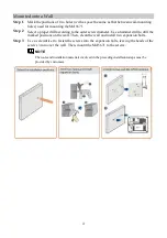
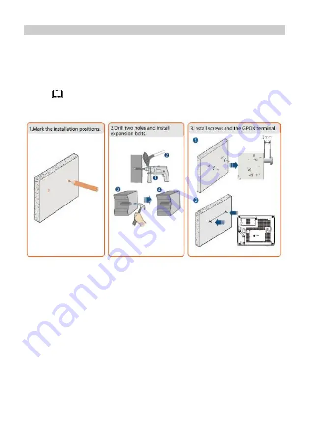
Step 1


Mark the positions of two holes (with a space the same as that between wall-mounting 
holes) used for mounting the MA5671. 

Step 2


Select a proper drill according to the outer screw diameter. Use a hammer drill to drill the 
marked positions on the wall. Then, clean the wall and install two expansion bolts. 

Step 3


Use a screwdriver to fasten the screws into the expansion bolts, leaving the heads of the 
screws 3 mm over the wall. Then, mount the MA5671 to the screws. 

NOTE


The tools and installation materials involved in the preceding installation steps must be 
provided by customers. 


Summary of Contents for SmartAX MA5671

Page 1: ...SmartAX MA5671 Desktop Multi service Access Equipment Quick Start ...

Page 2: ...d switch the device off before connecting or disconnecting cables Do not place any object on the device preventing the device from being damaged due to overheating or deformation Prevent objects such as metal or water from entering the device through the heat dissipation hole Switch the device off and disconnect all cables including the power cable network cable and phone cable during periods of l...

Page 3: ...ks Replace deteriorated cables or power socket facilities on the power supply line or near the device in a timely manner to eliminate safety risks 2 Installing the MA5671 NOTE Do not install the MA5671 outdoors or in an outdoor cabinet The MA5671 can be horizontally placed on a workbench or mounted onto a wall Do not install the MA5671 in other modes such as mounted to the ceiling Horizontally Pla...

Page 4: ...screw diameter Use a hammer drill to drill the marked positions on the wall Then clean the wall and install two expansion bolts Step 3 Use a screwdriver to fasten the screws into the expansion bolts leaving the heads of the screws 3 mm over the wall Then mount the MA5671 to the screws NOTE The tools and installation materials involved in the preceding installation steps must be provided by custome...

Page 5: ...5 3 Connecting Cables ...

Page 6: ... optical fiber connector connected to the OPTICAL port must be of the SC UPC type The bending radius of optical fibers must be greater than 30 mm in optical fiber deployment for proper optical fiber running Step 2 Use an Ethernet cable to connect the LAN port to network port on the PC or IP set top box STB Step 3 Use a power adapter to connect the POWER port to the power socket Step 4 Press ON OFF...

Page 7: ...ayed Step 3 In the login window enter the user name telecomadmin and password default admintelecom select a web page language and click Login After the password is authenticated the MA5671 s web page is displayed If you perform no operation within 5 minutes after logging in to the web page the MA5671 automatically returns to the login page The MA5671 is automatically locked if you incorrectly ente...

Page 8: ...been prohibited by the OLT 2 Blinking twice one second Off The MA5671 is attempting to connect to the OLT 3 Steady on Off The MA5671 has connected to the OLT 4 Off Blinking once two seconds The RX optical power of the MA5671 is lower than the optical receiver sensitivity NOTE According to Class B the optical receiver sensitivity is 28 dB If the RX optical power of the MA5671 is less than 28 dB the...

Page 9: ... the MA5671 Press Reset using a needle type object How can I restore factory defaults Press Reset using a needle type object for longer than 10s to restore factory defaults and reset the MA5671 If this indicator is off and then on the MA5671 restarts successfully 7 Technical Specifications Item Specifications Weight including the power adapter About 700 g Power supply for the integrated device 12 ...

Page 10: ...card carefully fill in the required information and preserve this card in good condition PERSONAL OR COMPANY FULL NAME Address Postal Code Telephone Number Email Product Type Product Serial Number Purchase Date Invoice Number Dealer s Name Dealer s Address Dealer s Telephone Preserve well No reissue Dealer s Seal ...

Page 11: ...used by the fact that the product is dismantled or altered by anyone that is not from a Huawei authorized service partner 3 The defects are caused by the fact that the product is used in a harsh environment that is not suitable for the operation of the product 4 The defects are caused by any force majeure including but not limited to fire earthquake lightning and tsunami 5 The defects are caused b...

Page 12: ...of Huawei Technologies Co Ltd All other trademarks and trade names mentioned in this document are the property of their respective holders Notice The information in this document is subject to change without notice Every effort has been made in the preparation of this document to ensure accuracy of the contents but all statements information and recommendations in this document do not constitute a...

Reviews: