RMS-SNMP01B SNMP Card
User Manual
3 Installation and Basic Settings
Issue 10 (2020-03-20)
Copyright © Huawei Technologies Co., Ltd.
6
3.3 Installing the SNMP Card
The methods for installing SNMP cards are the same on UPS2000-A-(1 kVA-3 kVA) and
UPS2000-G-(1 kVA-3 kVA). The SNMP card is installed in the optional card slot at the rear
panel of the UPS. To install an SNMP card, perform the following steps.
Procedure
Step 1
Remove the cover of the optional card slot at the rear of the UPS and keep the screws.
Step 2
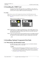
Insert the card into the optional card slot and secure the card using the screws, as shown in
Figure 3-1
Inserting the SNMP card into the slot
Step 3
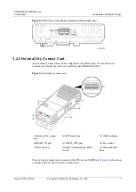
(Optional) If there is a temperature and humidity sensor, connect the RJ45 connector to the
port for monitoring the ambient temperature and humidity sensor on the SNMP card. For the
method about how to connect the other end of the cable, see the user manual related to the
temperature and humidity sensor.
Step 4
Connect one end of the network cable to the Ethernet network port on the SNMP card and the
other end to an Ethernet port. If the green indicator turns on and the yellow indicator blinks,
the SNMP card is successfully installed and is properly communicating with the Ethernet.
----End
3.4 Installing Optional ComponentsNewNode
3.4.1 Temperature and Humidity Sensor
The SNMP card supports temperature and humidity sensors. The ENR1DETA MODULE
temperature and humidity sensor is recommended.
If the SNMP card is equipped with a temperature and humidity sensor, you can view the UPS
temperature and humidity on the
Monitoring
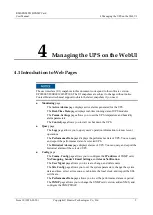
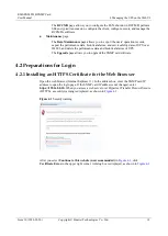
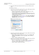
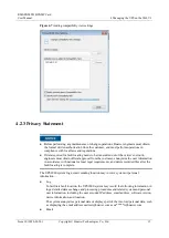
page on the WebUI of SNMP card, as shown in
. If the SNMP card is not equipped with a temperature and humidity sensor,
NA
is displayed.
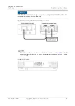
Set the temperature and humidity sensor address to 1 (DIP switch 1 is ON, the other DIP switch is
OFF, as shown in
) and baud rate to 9600.


