background image

3.2 Dimensions

NOTE

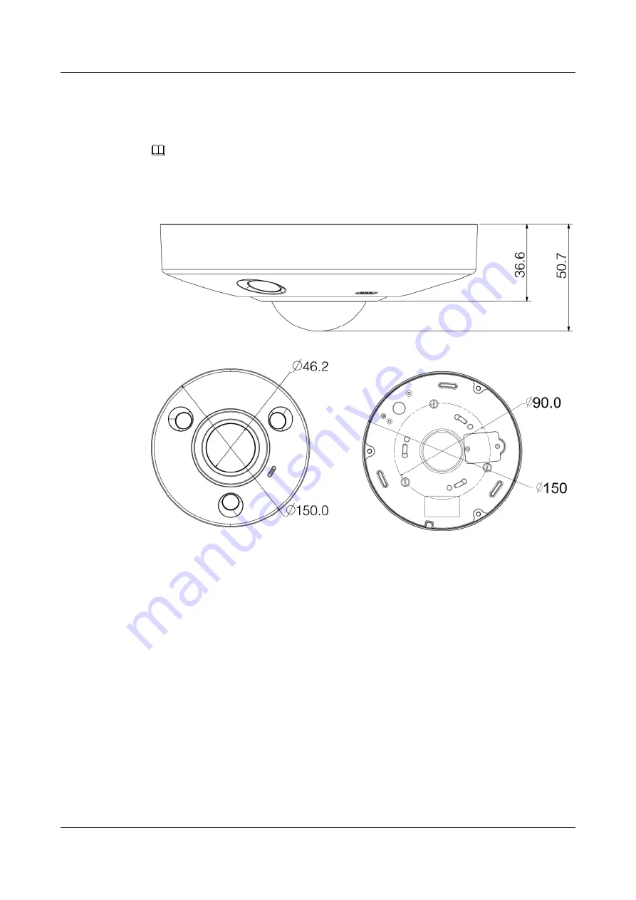
The side dimensions of the device are 36.6 mm x 50.7 mm, as shown in 

Figure 3-2

. Refer to the actual

product model for more details.

Figure 3-2

 Device dimensions (unit: mm)

IPC6061-FP
Quick Start Guide

3 Device Framework

Issue 01 (2019-02-22)

Copyright © Huawei Technologies Co., Ltd.

9

Summary of Contents for IPC6061-FP

Page 1: ...IPC6061 FP V300R019C00 Quick Start Guide Issue 01 Date 2019 02 22 HUAWEI TECHNOLOGIES CO LTD ...

Page 2: ...scribed in this document may not be within the purchase scope or the usage scope Unless otherwise specified in the contract all statements information and recommendations in this document are provided AS IS without warranties guarantees or representations of any kind either express or implied The information in this document is subject to change without notice Every effort has been made in the pre...

Page 3: ...ions 9 4 Installation 10 4 1 Optional Install the SD Card 10 4 2 Fix Device 11 4 3 Connect Device Cables 14 5 Network Configuration 17 5 1 Set the Initial Password 17 5 2 Modify IP Address 19 5 3 Login Web Interface 20 6 Warranty Card 21 IPC6061 FP Quick Start Guide Contents Issue 01 2019 02 22 Copyright Huawei Technologies Co Ltd ii ...

Page 4: ...19 6000 TAC Hotline 877 448 2934 FCC Compliance Statement for products subject to Part 15 This device complies with part 15 of the FCC Rules Operation is subject to the following two conditions 1 This device may not cause harmful interference and 2 this device must accept any interference received including interference that may cause undesired operation Symbol Conventions The symbols that may be ...

Page 5: ... disconnect device shall be incorporated in the building installation wiring l Prevent the power cable from being trampled or pressed especially the plug power socket and the junction extruded from the device Environment l Do not aim the device at strong light to focus such as lamp light and sun light otherwise it might cause over brightness or light marks which are not the device malfunction and ...

Page 6: ...he device together with lightning arrester to improve lightning protection effect l It is advised to get the grounding holes to be grounded to enhance the reliability of the device l Do not directly touch the optic component CCD or CMOS You can use the air blower to blow away the dust or dirt on the lens surface Please use a dry cloth wetted by alcohol to wipe away the dust gently if necessary l U...

Page 7: ...ly sources for the device otherwise it might damage the device Disclaimer l This manual is for reference only Please refer to the actual product for more details l Minor differences might be found in user interface and there might be deviation between the actual value of some data and the value provided in the manual due to the reasons such as the real environment is not stable Please refer to the...

Page 8: ...all the accessories are included For details see the accessory list delivered with the device For details about the configuration see the specific product documentation IPC6061 FP Quick Start Guide 2 Unpacking Inspection Issue 01 2019 02 22 Copyright Huawei Technologies Co Ltd 5 ...

Page 9: ...igure is for reference only It is only used to understand the functions of device external ports l There might be some minor differences between different devices so please refer to the actual products you purchased IPC6061 FP Quick Start Guide 3 Device Framework Issue 01 2019 02 22 Copyright Huawei Technologies Co Ltd 6 ...

Page 10: ...tion NOTE It may cause damage to the device if it fails to power the device according to label instruction 2 LAN Network port Ethernet port Connects to the standard Ethernet cable and provides PoE power supply NOTE Some devices do not support PoE power supply 3 AUDIO IN Audio input port RCA Receives analog audio signal from pickup and so on 4 AUDIO OUT Audio output port RCA Outputs audio signal to...

Page 11: ...t 1 ALARM_OUT1 Alarm output port 1 outputs alarm signal to alarm device NOTE ALARM_OUT1 can only be used with ALM_OUT_GND1 cooperatively when connecting to alarm device 2 ALM_OUT_GND1 3 ALARM_IN1 Alarm input port 1 receives on off signal of external alarm source 4 ALARM_IN2 Alarm input port 2 receives on off signal from external alarm source 5 ALM_IN_GND Alarm input GND terminal 6 ALARM_OUT2 Alarm...

Page 12: ... device are 36 6 mm x 50 7 mm as shown in Figure 3 2 Refer to the actual product model for more details Figure 3 2 Device dimensions unit mm IPC6061 FP Quick Start Guide 3 Device Framework Issue 01 2019 02 22 Copyright Huawei Technologies Co Ltd 9 ...

Page 13: ...e waterproof performance Please be sure to put the silica gel ring of the SD card cover back to the waterproof groove after the Micro SD card is installation completely l The Micro SD card shall be replaced within 4 hours otherwise it will cause desiccant failure and abnormalities such as water mist Step 1 Find SD card slot in the location which is shown in Figure 4 1 use a Phillips screwdriver to...

Page 14: ...use bracket to install the device on the ceiling which means there are three types of installation modes which are ground mount ceiling mount and wall mount The following chapter is an example of ceiling mount Before you complete the installation and debugging do not remove the electrostatic attraction film on the transparent enclosure Otherwise it may result in injury After removing the electrost...

Page 15: ...Figure 4 2 Installation Position Map Figure 4 3 Ceiling Mount Effect Figure 4 4 Wall Mount Effect IPC6061 FP Quick Start Guide 4 Installation Issue 01 2019 02 22 Copyright Huawei Technologies Co Ltd 12 ...

Page 16: ...go through Step 3 Insert 3 expansion bolts from the accessories bag into the bottom holes and lock them firmly adjust the position of device installation pedestal and pull the cable through the cable exit hole on the installation surface Step 4 Align 3 fixed holes of screw on the bracket with 3 plastic expansion bolt fixed holes on the installation surface then tighten 3 ST3 self tapping screws in...

Page 17: ...xternal cable according to Connect the Alarm Input Output Port and use insulated tape to twine connection to make it waterproof l Connect network cable to corresponding network port of the device cable according to Optional Install the Waterproof Connector Connect the Alarm Input Output Port Step 1 Connect alarm input device to the alarm input of I O port When the input signal is idle or grounded ...

Page 18: ...ce of alarm setup l Alarm input of Web is corresponding to the alarm input of I O port cable It is to set corresponding NO NC input according to the high and low level signal generated when alarm happens for alarm input device l Set alarm output on the Web alarm output is corresponding to the alarm output end which is the alarm output port of the I O port cable End Optional Install the Waterproof ...

Page 19: ...ixing rubber ring and waterproof locking cover make the crystal head of network cable and then insert it into the network cable Step 3 Put the main body of waterproof connector on the network port and rotate it clockwise to lock the network port and waterproof connector firmly Step 4 Put the waterproof locking cover on the main body of waterproof connector and rotate it clockwise to lock the water...

Page 20: ... the camera have access to network smoothly please plan available IP segment according to the actual network environment l The following figures are for reference only different models may have different interfaces 5 1 Set the Initial Password 5 2 Modify IP Address 5 3 Login Web Interface 5 1 Set the Initial Password Step 1 In the address box of Internet Explorer enter http IPC IP address and pres...

Page 21: ...t two kinds of them excluding Please set password with high security according to the password strong and weak prompt Step 3 Click OK The Online Upgrade page is displayed as shown in Figure 5 2 Figure 5 2 Online Upgrade Step 4 Deselect Auto check for updates Step 5 Click OK to complete device initialization End IPC6061 FP Quick Start Guide 5 Network Configuration Issue 01 2019 02 22 Copyright Huaw...

Page 22: ...3 Click Login The camera home page is displayed Step 4 Choose Setting Network TCP IP The system will display the Setting dialog box as shown in Figure 5 3 Figure 5 3 Setting the IP address Step 5 Set the Mode as Static and enter the planned start IP subnet mask and gateway NOTE Set the Mode as DHCP when there is DHCP server in the network the device will automatically acquire IP address from the D...

Page 23: ... are advised to access the camera web page by entering https camera IP address in the address box of your web browser Step 2 Please operate according to the interface prompt if the interface displays guide of Online Upgrade Step 3 Enter the user name and password and click Login Step 4 For the first login click Please click here to download and installthe plug in Install controls as prompted Step ...

Page 24: ...6Warranty Card IPC6061 FP Quick Start Guide 6 Warranty Card Issue 01 2019 02 22 Copyright Huawei Technologies Co Ltd 21 ...

Page 25: ...IPC6061 FP Quick Start Guide 6 Warranty Card Issue 01 2019 02 22 Copyright Huawei Technologies Co Ltd 22 ...

Reviews: