iManager NetEco 6000
Device Installation and Commissioning Guide
6 Adding Devices
Issue 03 (2019-03-10)
Copyright © Huawei Technologies Co., Ltd.
141
Step 2
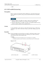
Hold down the networking switch on the BIM for 2 seconds. When the RUN/ALM indicator
turns from steady red to blinking green at super short intervals, and finally to blinking green at
long intervals, the BIM connects to the CIM network.
It is recommended that BIMs be networked from the positive battery string terminal according to the
battery cable connection sequence.
Batteries are numbered depending on the sequence of connecting BIMs to the CIM.
Step 3
Perform networking operations on the next BIM only after networking for the previous BIM
is successful. Repeat
to add remaining BIMs to the CIM network.
Step 4
Press the CIM networking switch for 2 seconds. When the RF_Z indicator on the CIM turns
from blinking green at super short intervals to blinking green at long intervals, the networking
is complete.
After the networking is complete, if the ALM indicator on the CIM is steady on, the number of devices
online is smaller than the value of BIM number. Check that BIM number is set to a correct value and
that the BIM is successfully networked.
Step 5
(Optional) If multiple CIMs are cascaded, repeat
to
remaining CIMs and BIMs.
----End
Follow-up Procedure
If the UPS does not charge batteries for a long time, power off the CIMs to prevent damage to
batteries. After the CIMs have been powered off for 30 minutes, the BIMs will hibernate
automatically if the voltage of 2 V batteries is less than 2.1 V or the voltage of 12 V batteries
is less than 12.6 V.
When the UPS is charging batteries, and the voltage of 2 V batteries is greater than 2.1 V or the
voltage of 12 V batteries is greater than 12.6 V, the BIMs will start automatically.
The battery voltage for enabling the BIMs to automatically hibernate or start varies under different
conditions.
6.3.2 Adding the Video Management System
Because cameras and VCN do not support northbound and southbound isolation, the VCN service IP
address must be set to a northbound IP address.
The camera IP address and the VCN service IP address must be in the same network segment.
For details about northbound IP address, see section
Overview of Southbound and Northbound
Network Isolation
in
iManager NetEco 6000 Product Documentation
.
6.3.2.1 Configuring VCN500 Server Parameters
6.3.2.1.1 Changing IP Addresses of VCN500 Servers
Context
A default IP address is configured for a VCN500 server before delivery. Users need to modify
the IP address based on the actual network planning.

