background image

FusionModule1000B Air-Cooled IT Solution 
Maintenance Guide 

6 Parts Replacement 


Issue 02 (2017-01-10) 

Huawei Proprietary and Confidential                                     

Copyright © Huawei Technologies Co., Ltd. 

123 


6.3.13.5 Replacing a Fingerprint Scanner 

Prerequisites 


A finger print scanner needs to be replaced.   


A spare finger print scanner of the same model is available and functional.   

Impact on the System 

None 

Preparations 

Tools: Phillips screwdriver, protective gloves 

Materials: spare fingerprint scanner 

Documents: documents delivered with the fingerprint scanner, management system initial 
configuration table, power supply and distribution system diagram 

Skill requirement: weak-current engineer 


For the diagrams and tables, see the initial configuration parameter manual for the solution in use. 

Procedure 

Step 1


Switch off the access controller circuit breaker in the PDB. 

Step 2


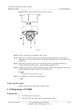
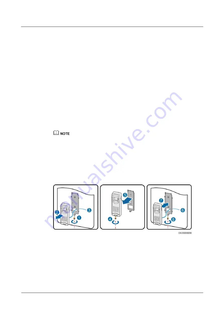
Remove screws securing the fingerprint scanner, and remove cables, as shown by (1), (2), and 
(3) i

Figure 6-41

. 

Figure 6-41


Replacing a fingerprint scanner 


Step 3


Remove the base plate of the new fingerprint scanner, as shown by (4) and (5) i

Figure 6-41

. 

Step 4


Connect cables, as shown by (6) i

Figure 6-41

. 

Step 5


Fix the fingerprint scanner onto the base plate, as shown by (7) and (8) i

Figure 6-41

. 

Step 6


Switch on the access controller circuit breaker in the PDB. 

Step 7


Configure the fingerprint scanner by referring to the management system initial configuration 
table and documents delivered with the fingerprint scanner. 

Summary of Contents for FusionModule 1000

Page 1: ...FusionModule1000B Air Cooled IT Solution V100R003C00 Maintenance Guide Issue 02 Date 2017 01 10 HUAWEI TECHNOLOGIES CO LTD ...

Page 2: ... Huawei and the customer All or part of the products services and features described in this document may not be within the purchase scope or the usage scope Unless otherwise specified in the contract all statements information and recommendations in this document are provided AS IS without warranties guarantees or representations of any kind either express or implied The information in this docum...

Page 3: ... This document is intended for Maintenance engineers Technical support engineers System engineers Hardware installation engineers Commissioning engineers Data configuration engineers Symbol Conventions The symbols that may be found in this document are defined as follows Symbol Description Indicates an imminently hazardous situation which if not avoided will result in death or serious injury Indic...

Page 4: ...related to personal injury equipment damage and environment deterioration Change History Changes between document issues are cumulative The latest document issue contains all updates made in previous issues Issue 02 2017 01 10 Replacing the PD510 Optimized the method Replacing the card reader Optimized the method Replacing the electronic lock Deleted the content Replacing fire extinguishing system...

Page 5: ...ling flowchart 9 3 3 2 Viewing and Collecting Alarm Information 9 3 3 3 Determining the Faulty Area and Alarm Severity 11 3 3 4 Locating and Rectifying Faults 11 3 3 5 Parts Replacement 12 3 3 6 Emergency Operation 13 3 3 7 Contacting Huawei Technical Support 15 4 Routine Maintenance 16 4 1 Paint Repair 16 4 2 Routine Maintenance 21 4 3 Monthly Maintenance 22 4 3 1 Power Supply and Distribution Sy...

Page 6: ... 58 5 5 Humidity Alarms 60 5 6 Door Sensor Alarms 61 5 7 Access Control Alarms 61 5 8 Water Intrusion Alarm 62 5 9 Hydrogen Alarm 63 5 10 Mains Outage 64 5 11 Communication Failure Alarms 64 5 12 SPD Alarm 65 5 13 PDU8000 MDU Alarms 66 5 14 ATS Alarms 67 5 15 UPS5000 E Alarms 68 5 16 35 kW Air Cooled Precision Air Conditioner Alarms 69 5 17 20 kW Air Cooled Precision Air Conditioner Alarms 73 6 Pa...

Page 7: ...acing a LAN Switch 111 6 3 11 Replacing the ECC500 Collector 113 6 3 12 Replacing an RH2288 Server 115 6 3 13 Replacing Access Control Components 116 6 3 13 1 Replacing a Card Reader 116 6 3 13 2 Replacing an Exit Button 118 6 3 13 3 Replacing an Electronic Lock 119 6 3 13 4 Replacing an Emergency Door Release Button 121 6 3 13 5 Replacing a Fingerprint Scanner 123 6 3 13 6 Replacing an Access Con...

Page 8: ... 178 7 Emergency Operations 181 7 1 Emergency Operations for Mains Failure 181 7 2 Emergency Operations for Circuit Breaker Tripping 182 7 3 Overload Emergency Operations 183 7 4 Emergency Operations for Battery Electrolyte Leakage 183 7 5 Emergency Operations for Overtemperature 184 7 6 Emergency Operations for the Management System Communication Failure 184 7 7 Emergency Operations for High Hydr...

Page 9: ...cs or sparks which may cause fire or hurt human eyes Before removing component cables mark the cables with their corresponding port numbers for later connection Before connecting a power cable check that the label on the power cable is correct For the detailed power control relationships between devices see the power distribution system diagram for the solution in use During battery O M observe th...

Page 10: ...itoring System Assign only professional engineers to perform O M for the management system Routine maintenance for the management system is critical for long term stable and efficient operation of the FusionModule1000 because most alarms are reported over the management system Promptly handle reported alarms to prevent equipment damage or service interruption Check and calibrate the hydrogen detec...

Page 11: ...ht Huawei Technologies Co Ltd 3 2 O M Preparations 2 1 Tools Before the O M obtain tools and materials listed in Table 2 1 Table 2 1 Tools Tools Phillips screwdriver Flat head screwdriver Adjustable wrench Electrician s knife Needle nose pliers Diagonal pliers Crimping tool Wire stripper RJ45 crimping tool Cable cutter Hex key Socket wrench ...

Page 12: ...graph Multimeter Electroprobe Network cable tester Heat gun Utility knife Step ladder 2 m Cable tie Insulation tape ESD wrist strap ESD gloves Protective gloves Clamp meter ESD floor suction plate Vacuum cleaner The listed tools are for routine maintenance only Prepare other tools as required 2 2 Obtaining Technical Documents Table 2 2 lists the technical documents required for FusionModule1000 O ...

Page 13: ... power on commissioning and power off shutdown for the FusionModule1000 Download this document from http e huawei com iManager NetEco Product Document NetEco Version Describes how to install the monitoring hardware and configure the monitoring software The NetEco version depends on the version in use Click on the NetEco WebUI to obtain the NetEco version If the NetEco version is iManager NetEco V6...

Page 14: ...available contact the local GTAC or TAC 2 3 Container Entry Requirements The following describes the requirements for working in the FusionModule1000 Item Requirement Before entry Obtain the entry permit NOTE The detailed operations are performed based on the requirements specified by the manager of the FusionModule1000 Entry preparations Obtain ESD clothes and shoes Remove dust from tools and mat...

Page 15: ...pply and distribution system configurations and the operations for each core component in the FusionModule1000 With power distribution system engineer qualifications Cooling System Familiar with the cooling system configurations and the operations for each core component in the FusionModule1000 With cooling engineer qualifications Management system With extra low voltage ELV engineer qualification...

Page 16: ...tine Maintenance Purpose Routine maintenance refers to preventive and periodic checking and maintenance carried out to promptly identify and handle alarms and potential faults during the normal running of the system Routine maintenance aims to ensure long term stable operation of the equipment By routine maintenance maintenance personnel can Promptly find and handle alarms related to equipment ope...

Page 17: ...rs and may jeopardize the long term stable running of the FusionModule1000 the system or a component will generate alarms O M personnel or the person on duty must promptly handle any identified alarms 3 3 1 Alarm handling flowchart Figure 3 1 Alarm handling flowchart 3 3 2 Viewing and Collecting Alarm Information Prerequisites An alarm is generated Alarm information helps to rapidly locate and rec...

Page 18: ...ssword If the password was not changed when the management system was commissioned enter the initial password Step 2 Choose Fault Current Alarms and view the current alarm information Step 3 Collect alarm information After an alarm is generated immediately collect the following information Occurrence time and place Detailed fault symptoms Operations performed before the fault occurs Services and s...

Page 19: ... in 5 Alarms and Faults Critical alarms include the following Alarms that cause system shutdown Alarms that result in equipment damage or affect equipment usage Alarms that may result in serious results such as fire or communication interruption 3 3 4 Locating and Rectifying Faults Locating Faults Locate faults from the following aspects Component Locate the component for which the alarm is genera...

Page 20: ...er infrastructure alarm reference in the online help of the management system Alarm references in documents delivered with components Alarm reference in this document Alarm reference obtained from Huawei technical support It is recommended that the alarm handling report consists of information about the alarm occurrence time location symptom fault locating process alarm handling process and alarm ...

Page 21: ...ncy operations For more emergency operations for the FusionModule1000 contact Huawei technical support FusionModule1000 Common Critical Alarms and Faults Table 3 2 describes the common critical alarms and faults in the FusionModule1000 Table 3 2 Common critical alarms and faults Common Critical Alarm and Fault Possible Cause Possible Impact Emergency Operation The mains supply is cut off The mains...

Page 22: ...ty The circuit is faulty O M personnel cannot go into or out of the container 7 8 Emergency Operations for Container Door Cannot Open Container Door Open Alarm The container door is open Safety of the equipment may be affected 7 9 Emergency Operations for Container Door Open Early fire alarm There is too much dust in the air A fire occurs 7 10 Emergency Operations for an Early Fire Alarm Single Fi...

Page 23: ...rmation You can obtain technical support from Huawei over the network or telephone For details see Table 3 3 Table 3 3 Obtaining technical support from Huawei If Then Method A critical alarm is generated Refer to the emergency operation guide Clear the alarm by following the procedure described in the emergency operation guide If no information is available contact Huawei technical support Contact...

Page 24: ...age to the container paint and prepare appropriate tools and materials The number of materials depends on site requirements Table 4 1 Paint repair Paint Damage Tools and Materials Procedure Description Slight scratch steel base material not exposed Spray paint or paint brush required for repainting a small area fine sandpaper anhydrous alcohol cotton cloth painting gun required for repainting a la...

Page 25: ...ating The surface should be smooth 5 Leave the repainted area for about 30 minutes before performing any further operation LOGO and pattern damage Seek help from Huawei headquarters for a detailed painting solution Frontline personnel can turn to local advertisement coating suppliers Dent 1 If a dent is less than 100 mm2 in area and less than 3 mm in depth fill the dent with Poly Putty base and th...

Page 26: ...Polishing a damaged area using sandpaper Step 2 Dip a piece of cotton cloth into anhydrous alcohol and wipe the polished or damaged area to remove the dirt and dust Then wipe off the alcohol with a clean and dry cotton cloth Figure 4 2 Wiping a polished or damaged area using anhydrous alcohol Step 3 Paint zinc rich primer on the damaged coat using a brush or painting gun initial painting ...

Page 27: ...inish coat based on the damage degree of the paint described in Table 4 1 using a spray bottle brush or painting gun respectively shown in Figure 4 4 Figure 4 5 and Figure 4 6 In the case that a container pattern has different colors to prevent undamaged areas and those with different colors as the damaged area from being polluted during repainting cover such areas using white paper and adhesive t...

Page 28: ...nting gun End Follow up Procedure Check whether the surface meets the requirement after repainting The repainted area should have the same color as surrounding areas The color difference δE is not greater than 3 Use a colorimeter to measure the color difference If a colorimeter is not available check that no obvious edge exists between the repainted area and its surrounding The paint should also b...

Page 29: ...ent right click a camera name on the right side and view the video images captured by the camera The video images are properly displayed If no video image is displayed 1 Connect the camera cable again 2 If the cable is correctly connected replace the camera by following instructions in 6 3 8 Replacing a Camera If the camera is normal but no video image is displayed 1 Connect the VCN500 cable again...

Page 30: ... 1 Power Supply and Distribution System Table 4 3 Monthly maintenance checklist for the power supply and distribution system Item Method Expected Result Troubleshooting PDC Check the indicator The three phase power indicators are steady on If an indicator is off or dim replace it by following instructions in the PDC user manual Check the SPD indicator and SPD circuit breaker status The SPD indicat...

Page 31: ...l of the UPS5000 E The status icons on the LCD indicate that all units are operating properly all operating parameters are within their normal ranges and no fault or alarm information is displayed If an alarm is present refer to the UPS5000 E alarm reference to check the device status and parameters UPS5000 E batteries View batteries The battery shell is intact without acid leaks deformatio n or b...

Page 32: ...g system Item Method Expected Result Troubleshooting 20 kW air cooled precision air conditioner Check electric heaters The electric heaters and switches are secure Secure the electric heaters and switches The electric heater surface is not corroded Replace the faulty electric heater by following instructions in the air conditioner user manual Check the floats There is no scale Clean the floats The...

Page 33: ...g instructions in the air conditioner user manual 35 kW air cooled precision air conditioner Check air filters No dust is accumulated on air filters Clean dust from the air filters using a brush or vacuum cleaner The air filters are not damaged or misshapen Replace by following instructions in 6 2 3 Replacing Air Filters for a 35 kW Air Cooled Precision Air Conditioner Listen to the compressor ope...

Page 34: ...he cooling circuit to check whether there are oil stains There is no oil stain Check whether the air suction and exhaust pressure of the compressor is within the normal ranges If no contact Huawei technical support Check the pipes of the humidifier cylinder There is no water stain under pipes If drops of water are evenly distributed wipe off them with a dry cloth If there are dense water stains id...

Page 35: ...ensor The water sensor is secure and the two downward metal conductive plates do not touch with each other and are free from corrosion Replace the faulty water sensor by following instructions in the air conditioner user manual Thermal insulation foam for the humidifier condensate drainpipe Check whether the thermal insulation layers are in good condition without condensation The thermal insulatio...

Page 36: ...dicator is steady green See the documents delivered with the VCN500 Access control system Swipe a card to open the door When an access card is swiped the card reader indicator blinks green once and then returns to steady red You will hear a beep Swipe another access card and observe the door status If the door can be opened by another access card the original access card is damaged Prepare a new a...

Page 37: ...rroded terminals by referring to 6 4 8 Replacing Batteries for the Fire Alarm Control Panel Standard or 6 6 Replacing Batteries for the VESDA Power Box Fire extinguishe r Check the appearance of the fire cylinder electromagnetic valve pipeline and nozzle All devices of the fire extinguisher are intact free from deformation and mechanical damage Replace the fire cylinder by following instructions i...

Page 38: ...lacing an Emergency Light Standard Smoke detector Check the smoke detector indicator The indicator blinks once every 6s Replace by following instructions in 6 4 1 Replacing a Smoke Detector Standard Heat detector Check the heat detector indicator The indicator blinks once every 6s Replace by following instructions in 6 4 2 Replacing a Heat detector Standard 4 3 5 Fire Extinguishing System CE Table...

Page 39: ...inder The pressure pointer is in the green zone Ask a fire engineer to check whether the fire cylinder leaks extinguishant If leakage occurs the fire engineer charges the extinguishant in the local charging station Emergency light Disconnect the power plug of the emergency light The emergency light turns on Replace by following instructions in 6 5 11 Replacing an Emergency Light CE Smoke detector ...

Page 40: ...act Cables and cable trays are intact without serious aging Replace seriously aged cables For details see the installation guide for the solution in use External environmen t of containers Check whether hazards or potential hazards exist around the containers No hazard or potential hazard exists around the containers Take measures to handle potential hazards Check whether obvious rubbish exists ar...

Page 41: ...the UPS5000 E initial configuration table Check whether the system is clean There is no dust on the surface Clean the dust Check the power cables and terminals Cables and terminals are free from deterioration damage spark signs and loose contacts Replace cables or secure output terminals UPS5000 E batteries View battery management alarms No battery management alarm is generated Identify the cause ...

Page 42: ... fan by following instructions in the air conditioner user manual The fan blades are intact Replace the faulty indoor fan by following instructions in the air conditioner user manual Check the running sound of the indoor fan No abnormal noise is generated Replace the faulty indoor fan by following instructions in the air conditioner user manual Check screws securing the indoor fan The indoor fan i...

Page 43: ...ed replace it by following instructions in the air conditioner user manual If the water inlet pipe is blocked clean the pipe If the humidifier cylinder is dirty and the water level inside the cylinder exceeds the 4 5 line replace the humidifier cylinder by following instructions in the air conditioner user manual Check the thermal insulation foam of the water inlet pipe drainpipe and vapor hose of...

Page 44: ...and they cannot be cleaned up replace the water pump by following instructions in the user manual delivered with the water pump Start the air conditioner choose Maint Diagnostic Mode Enter from the main screen and set Electric heater to On Check whether the electric heater generates heat The electric heater generates heat Replace the faulty electric heater by following instructions in the air cond...

Page 45: ...uch as metal friction sound Replace the faulty compressor by following instructions in the air conditioner user manual Check whether the heat exchanging coil is dirty and blocked No foreign matter exists on the heat exchanger surface Remove foreign matter Check fans The fan blades are intact and generate no abnormal sound during operation Replace the faulty fan by following instructions in the air...

Page 46: ...eck the alarm information displayed on the monitoring software terminal The management system generates a door status alarm If no alarm is generated replace by following instructions in 6 3 4 Replacing a Door Status Sensor Access controller Check the power indicator of the access controller The power indicator is steady red If the indicator is off the power supply to the access controller is abnor...

Page 47: ...ether the fuse is intact If the fuse is blown replace the fuse 2 Perform replacement by following instructions in 6 4 8 Replacing Batteries for the Fire Alarm Control Panel Standard Hand held fire extinguishe r Check the fire extinguisher The fire extinguisher is intact Replace the fire extinguisher The pressure pointer of the fire extinguisher is in the green zone Replace the fire extinguisher Th...

Page 48: ...od condition Replace the hand held fire extinguisher The pressure pointer of the hand held fire extinguisher is in the green zone The fire extinguisher is within the validity period 4 4 6 Other Systems Table 4 14 Quarterly maintenance checklist for other systems Item Method Expected Result Troubleshooting Container body Check the container The container is clean 1 Clean the container using a long ...

Page 49: ...dicator is on 1 If the panel indicator is off verify that the power cable is properly connected 2 Replace the ATS by following instructions in documents delivered with the ATS The controller display panel displays information properly 1 If the information is not properly displayed fuzzy or blank verify that the power cable is properly connected 2 Replace the ATS by following instructions in docume...

Page 50: ... green None If the indicator is off the power supply unit PSU is not detected or the power supply to the board is abnormal when the switch is configured with one PSU Check the power supply If the power supply is normal replace by following instructions in 6 3 10 Replacing a LAN Switch The PWR indicator is steady red If the PWR indicator is steady red Check whether two PSUs are configured and switc...

Page 51: ...dy red the LAN switch is not running properly after device registration Contact Huawei technical support Water sensor point type Dip the water sensor into water and view alarms in the management system The management system generates an alarm If no alarm is generated replace by following instructions in 6 3 2 Replacing a Water Sensor Point Type Water sensor rope type Drip a small amount of water o...

Page 52: ...ipe another access card and observe the door status If the door can be opened by another access card the original access card is damaged Prepare a new access card and assign permission to the card If the door cannot be opened replace by following instructions in 6 3 13 1 Replacing a Card Reader Optional Read your fingerprint to open the door after your fingerprint has been collected and assigned t...

Page 53: ...aust fan is working properly 1 Check and reconnect cables to the hydrogen exhaust fan 2 If the fault persists replace by following instructions in 6 3 7 Replacing a Hydrogen Exhaust Fan Calibrate the sensitivity of the hydrogen detector 1 When the default screen is displayed on the transducer LCD hold down FUNC for more than 5s using a magnetic bar and release the button 2 After the Parameter sett...

Page 54: ... has been running for a whole year In this way the sensitivity of the hydrogen detector is linearly corrected and compensated Calibrate the correction value of the hydrogen detector 1 When the default screen is displayed on the transducer LCD hold down FUNC for more than 4s using a magnetic bar and release the button 2 After the Parameter setting menu is displayed the LCD turns purple and Calibrat...

Page 55: ... stop working Before the maintenance disconnect all cables to fire cylinder electromagnetic valves to avoid extinguishant release and damage to equipment due to misoperations After the maintenance reconnect the cables to fire cylinder electromagnetic valves and inform the administrative departments that the fire extinguishing system has resumed Table 4 18 Semi annual maintenance checklist for the ...

Page 56: ...ciator The gas release indicator is on Replace by following instructions in 6 4 3 Replacing the Gas Release Indicator Standard Heat detector Heat the heat detector using a heating device If the temperature is below the alarm threshold 54 70 C the gas release indicator blinks once every 6 seconds If the fault persists replace by following instructions in 6 4 2 Replacing a Heat detector Standard If ...

Page 57: ... the fire alarm horn strobe does not react replace by following instructions in 6 4 5 Replacing an External Horn Strobe Standard or 6 4 4 Replacing an Indoor Fire Alarm Horn Strobe Standard VESDA Check the VESDA sampling pipes The supports and connectors of the sampling pipes are securely connected Replace damaged sampling pipes and apply glue where pipes are not well sealed Remove or block a samp...

Page 58: ...ve of the fire cylinder This prevents the extinguishant release due to misoperations and prevents accidental damage After the maintenance reconnect the electrical actuator and inform the administrative departments that the fire extinguishing system has become operational Table 4 19 Semi annual maintenance checklist for the fire extinguishing system Device Operation Check Standard Maintenance Guide...

Page 59: ... is above the alarm threshold the indicator turns on The extinguishant control panel generates an alarm and triggers the fire alarm bell Replace by following instructions in 6 5 2 Replacing a Heat Detector CE Smoke detector Release smoke onto the smoke detector using a smoke pistol 1 If the smoke density is below the alarm threshold the alarm indicator blinks once every 6s 2 If the smoke density i...

Page 60: ... securely connected Replace damaged sampling pipes and apply glue where pipes are not well sealed Remove or block a sampling pipe An alarm is generated See documents delivered with the VESDA Release smoke to the furthest end of a VESDA sampling pipe The VESDA generates an alarm in 120s See documents delivered with the VESDA The VESDA panel displays an alarm See documents delivered with the VESDA C...

Page 61: ...f more than 50 of the meshes are blocked perform replacement by following instructions in 6 2 5 Replacing a Ventilation Vent Air Filter Cable trays inside containers Check whether the cable trays are securely connected without damage or misshapen Cable trays are properly installed and fasteners are secure Secure cable trays that have become loose Cable trays screws and nuts are free from rust or c...

Page 62: ...no dust on the surface Clean the dust UPS5000 E Check the power cables and terminal connections between the UPS and the PDC Cables and terminals are free from deterioration damage spark signs and loose contacts Replace cables or secure output terminals UPS5000 E battery Check whether the equalized charging voltage and float charging voltage of a battery are normal Equalized charging voltage 2 35 V...

Page 63: ...xhaust fan Shut down the fan and check whether the air filter is blocked The air filter is not blocked If an air filter is slightly blocked clean the air filter and reinstall it If more than 50 of the meshes are blocked perform replacement by following instructions in 6 2 5 Replacing a Ventilation Vent Air Filter T H sensors with LCD Check the T H sensors against specifications on their labels The...

Page 64: ...ential Copyright Huawei Technologies Co Ltd 56 Categ ory Item Method Expected Result Troubleshooting racks are properly connected to cable trays Check whether the cable trays and their supports are properly connected to the ground grid free from rust The ground bolts are securely grounded and free from rust anti corrosion measures ...

Page 65: ... air and the sampling pipe is blocked Clean the sampling pipe Something is smoldering in the container Troubleshoot by referring to 7 10 Emergency Operations for an Early Fire Alarm 5 2 Fire Alarms Standard Fault Category Alar m Sever ity Operation Single fire Critica l For details about how to handle a single fire alarm see 7 11 Emergency Operations for a Single Fire Alarm Standard Double fire Cr...

Page 66: ...OCAL FIRE alarm see 7 14 Emergency Operations for a LOCAL FIRE Alarm CE FAULT RELAY Major See the documents delivered with the extinguishant control panel A fire can seriously affect the stable running of the system and equipment safety Therefore any fire alarm must be immediately handled 5 4 Temperature Alarms Fault Category Alar m Sever ity Symptom Possible Cause Troubleshooting Overtemp erature...

Page 67: ...d exceeds the designed cooling capacity For details see 7 3 Overload Emergency Operations The onsite temperature is normal The T H sensor is faulty Replace by following instructions in 6 3 1 Replacing a Polymer T H Sensor Undertem perature Inform ation The onsite temperature is too low The load ratio is too low Shut down some air conditioners The onsite ambient temperature is too low The air suppl...

Page 68: ...s normal The T H sensor is faulty Replace by following instructions in 6 3 1 Replacing a Polymer T H Sensor The humidity threshold is not properly set Verify that the configured temperature and humidity thresholds are consistent with the T H sensor initial configuration table in the initial configuration parameter manual The onsite humidity is too high The load ratio is too low Shut down some air ...

Page 69: ...or and check whether the alarm is cleared 2 If the alarm persists troubleshoot by following instructions in 7 9 Emergency Operations for Container Door Open 5 7 Access Control Alarms Fault Category Alar m Sever ity Symptom Possible Cause Troubleshooting Access control alarm Critica l The door status cannot be controlled The access controller is faulty Verify the access controller cable connections...

Page 70: ...lacing the Humidifier Water Refill Pipe for a Precision Air Conditioner The condensate drainpipe is damaged Replace by following instructions in 6 2 7 2 Replacing the Condensate Drainpipe of a Precision Air Conditioner The condensate drainpipe is blocked Remove the drainpipe outside the container and dig out the material blocking the pipe using a thin iron wire The dehumidifier drainpipe is damage...

Page 71: ...collector is faulty Replace the hydrogen collector by following instructions in documents delivered with the hydrogen collector The hydrogen exhaust fan does not rotate or rotates slowly Cables of the hydrogen exhaust fan are not properly connected Verify the cable connections The hydrogen exhaust fan is faulty Replace by following instructions in 6 3 7 Replacing a Hydrogen Exhaust Fan All hardwar...

Page 72: ... an action does not take effect The PDC circuit breaker is faulty Contact Huawei technical support 5 11 Communication Failure Alarms Fault Category Alar m Sever ity Symptom Possible Cause Troubleshooting PD510 communic ation failure Major Real time monitoring cannot be performed Cables are not properly connected Verify the cable connections Powered on the power distribution equipment where the ele...

Page 73: ...or Real time monitoring cannot be performed Cables are not properly connected Verify the cable connections The device is faulty Replace by following instructions in 6 3 9 Replacing a VCN500 ECC500 communic ation failure Major Real time monitoring cannot be performed Cables are not properly connected Verify the cable connections The device is faulty Replace by following instructions in 6 3 11 Repla...

Page 74: ...rly connected Check that cables are properly connected The monitoring board or current transformer is faulty If the monitoring board or current transformer is faulty replace the faulty monitoring board or current transformer Major The user interface fails to display the circuit breaker status The communications cable of the Boolean value collection module or the corresponding branch Boolean value ...

Page 75: ... the monitoring board by following instructions in documents delivered with the PDU8000 For other PDU8000 alarms see documents delivered with the product 5 14 ATS Alarms Fault Category Alar m Sever ity Symptom Possible Cause Troubleshooting ATS alarms Inform ation The switchover fails The control terminals are not properly connected Properly connect the terminals The voltages of both power supplie...

Page 76: ... The power module is faulty Major The buzzer buzzes the Fault indicator is on the inverter is faulty and the UPS transfers to bypass mode Output overload or short circuit exists Reduce loads or troubleshoot the short circuited load The UPS5000 E inverter temperature exceeds the upper threshold Install more air conditioners or ventilation devices to ensure normal temperatures inside the equipment r...

Page 77: ...eaker fuses and cables The compressor motor is damaged Check whether the motor is damaged and needs replacing The compressor does not need to start Check for the requirement status on the LCD Major The compressor exhaust temperature is too high The refrigerant loop or component is blocked Clean up foreign matter from the refrigerant loop The outdoor unit is not properly installed Properly install ...

Page 78: ...ric heater temperature switch is protected Check whether the temperature switch of the electric heater is faulty and replace the switch if it is faulty The electric heater circuit breaker is switched off The electric heater circuit breaker is switched off Check the electric heater circuit breaker The electric heater burns out The electric heater burns out Disconnect the power supply and check whet...

Page 79: ...Check whether the floats are working properly and replace a float if necessary The inlet pipe or drainpipe leaks Check the inlet pipe and drainpipe and their connectors and repair leakage points The self drain pipe is blocked Check whether the self drain port is blocked and whether the self drain pipe contains foreign matter or is frozen Major The humidifier is faulty In the commissioning or runni...

Page 80: ...peration If the current exceeds 6 A the humidifier circuit breaker automatically trips 2 If the current is normal check that the current transformer and its cables are in good condition The water level decreases gradually but the humidifier cylinder does not work and no manual drainage is in progress Manually start the drainage valve several times If the problem persists replace the drainage valve...

Page 81: ...The compressor does not need to start Check whether cooling is required on the controller home page The power supply for the compressor is faulty Check that the compressor input power is normal Remove the X115 compressor terminals measure the terminal voltages at the connection surfaces If voltages between terminals 1 and 2 2 and 3 and 1 and 3 are within 10 of the rated voltage the input power sup...

Page 82: ... Huawei technical support Major An indoor fan does not work A fan alarm is generated Check whether an alarm is generated If yes handle the alarm by referring to the alarm reference list The fan does not need to work Choose Running Status on the controller home screen and check the indoor fan control status If the control status is 0 the fan does not need to work and there is no fault If the contro...

Page 83: ...ether the QF4 switch on the power subrack is turned on If yes go to the next step 2 Open the front door and check whether the fan fuse at the bottom is blown fuses FU9 FU16 from the top to the bottom are for fans 1 8 respectively If a fuse is blown replace it Major Water overflows The drainpipe is not properly connected Verify that the drainpipe is connected A float switch is faulty Check the floa...

Page 84: ...ver ity Symptom Possible Cause Troubleshooting repair the leakage point The drainpipe is blocked or the drainage solenoid is faulty Check whether the drainpipe is blocked by foreign matter or scale If yes close the water refill port drain water from the water pan and remove the blockage For other alarms generated for the 20 kW air cooled precision air conditioner see the air conditioner user manua...

Page 85: ...ctricity meter of the same model is available and functional Impact on the System Certain services in the FusionModule1000 are interrupted Preparations Tools Phillips screwdriver protective gloves Materials spare PD510 electricity meter Documents documents delivered with the PD510 electricity meter management system initial configuration table Skill requirement power distribution system engineer F...

Page 86: ...nal block and ensure that the terminal block is connected properly Step 6 Optional Install the panel of the PD510 electricity meter Step 7 Configure the address and baud rate of the PD510 by referring to the management system initial configuration table Step 8 Configure the PD510 electricity meter by following instructions in documents delivered with the PD510 electricity meter Step 9 Check that t...

Page 87: ...ications cables connected to the MDU as shown in Figure 6 2 Step 2 Remove the four screws fixing the MDU using a Phillips screwdriver and set them aside as shown in Figure 6 2 Figure 6 2 Removing the MDU Step 3 Hold the MDU front panel by one hand and push out the MDU from the fastener on the front panel by the other hand Step 4 Align the new MDU with the mounting holes snap the bottom of the new ...

Page 88: ... Prerequisites Do not replace an SPD during a thunderstorm An SPD is faulty A spare SPD of the same model is available and functional Impact on the System None Preparations Tools Phillips screwdriver flat head screwdriver electroprobe Materials spare SPD Documents required PDC user manual Skill requirement electrician s work permit Procedure Step 1 Remove the protective panel of the SPD Avoid touc...

Page 89: ...PD module it is recommended that all SPD modules be replaced If the SPD module cannot be pulled out use a tool such as a flat head screwdriver to lever it out Step 5 Install the spare SPD module and switch on the SPD module circuit breaker Step 6 Reinstall the protective panel End Follow up Procedure Dispose of the removed SPD module that is confirmed faulty 6 1 4 Replacing a UPS5000 E Battery Pre...

Page 90: ...p 2 Switch off the circuit breaker of the battery in the switch box based on the power supply and distribution system diagram Step 3 Remove cables from the faulty battery using a wrench and insulate the cables Step 4 Move the faulty battery out of the battery rack Step 5 Install the new battery and connect cables based on the UPS5000 E battery wiring diagram Step 6 Verify the battery connections E...

Page 91: ...nd unplug devices powered by the rPDU Step 3 Remove the monitoring rPDU using a Phillips screwdriver Figure 6 5 Removing screws Step 4 Replace the monitoring rPDU connect the industrial connectors and bind the cables using cable ties Step 5 Check that the new rPDU is working properly Step 6 Insert device power plugs in the rPDU Step 7 Restart devices shut down in Step 1 after verifying that the ne...

Page 92: ...tch off the circuit breaker of the faulty rPDU in the PDC Step 2 Remove all power connectors from the rPDU Step 3 Remove the baffle plate from the top of the cabinet using a Phillips screwdriver Step 4 Remove the rPDU power cable on the top of the cabinet Step 5 Loosen the screws securing the rPDU support at the top and bottom of the rPDU using a Phillips screwdriver until the rPDU can be removed ...

Page 93: ...Switch on the circuit breaker for the rPDU in the PDC and check that the new rPDU is working properly Step 11 Insert device power plugs in the rPDU Step 12 Reinstall the cabinet top baffle plate End Follow up Procedure Dispose of the removed rPDU that is confirmed faulty 6 2 Replacing Cooling System Components 6 2 1 Replacing a Remote T H Sensor for an Air Conditioner Prerequisites A remote T H se...

Page 94: ... sensor Step 2 Remove the faulty remote T H sensor install a new remote T H sensor and reconnect the network cables to the sensor Step 3 Set the DIP switch for the remote T H sensor by referring to the remote T H sensor DIP switch initial configuration table Step 4 Check that the new remote T H sensor is working properly If the indicator of the remote T H sensor is on and the air conditioner LCD d...

Page 95: ...be replaced with power on However it is recommended that you power off the air conditioner before replacing an air filter Procedure Step 1 Tap Shutdown on the controller home screen and switch off the upstream circuit breaker Step 2 Remove the rear door rotate the fixing cards on the two sides of the air filter as shown by 1 in Figure 6 9 Step 3 Pull out the air filter as shown by 2 in Figure 6 9 ...

Page 96: ... Air Cooled Precision Air Conditioner Prerequisites The air conditioner air filters need to be replaced Spare air filters of the same model are available and functional Impact on the System None Preparations Tool protective gloves Materials spare air filter Documents required none Skill requirement cooling engineer Air filters can be replaced with power on However it is recommended that you power ...

Page 97: ...he same way Step 5 Install a new air filter Do not touch the pressure tube during the replacement and verify that the pressure tube is correctly connected after the replacement Install air filters as instructed by the labels to avoid reverse installation Step 6 Switch on the upstream circuit breaker and tap Start on the home screen after the controller is powered on Step 7 Choose Maint Performance...

Page 98: ...ditioner may need to be powered off Take measures to prevent device overheating Table 6 1 and Table 6 2 lists the parts that can be replaced for an air cooled precision air conditioner Table 6 1 Parts that can be replaced for a 20 kW precision air conditioner No Item 1 Air filter 2 Indoor fan 3 Compressor 4 Humidifier cylinder 5 Electric heater 6 Solenoid valve coil 7 Components inside the control...

Page 99: ... 6 2 5 Replacing a Ventilation Vent Air Filter Prerequisites An air filter needs to be replaced A spare air filter of the same model is available and functional Impact on the System None Preparations Tool Phillips screwdriver step ladder brush Materials spare air filter Documents required none Skill requirement cooling engineer Procedure Step 1 Remove screws securing the air filter using a Phillip...

Page 100: ... glue for installing thermal insulation foam tinfoil adhesive brush protective gloves ESD floor suction plate Materials thermal insulation foam dry rag Documents required none Skill requirement cooling engineer Procedure Step 1 Optional Open the aisle floor using the ESD floor suction plate Step 2 Remove the straps and thermal insulation foam from a pipe Step 3 Wipe off the condensate water from t...

Page 101: ...placing the Humidifier Water Refill Pipe for a Precision Air Conditioner Prerequisites A humidifier water refill pipe needs to be replaced A spare humidifier water refill pipe of the same model is available and functional Water refill devices are available Impact on the System None Preparations Tools hex key long sleeved silicone gloves vessel adjustable wrench ESD floor suction plate Materials dr...

Page 102: ... in the pipe to the vessel Step 5 Install a new water refill pipe Check that the safety clamp is secured and that the water pipe does not leak Step 6 Open the water supply valve wait until the new pipe is working properly and wrap the new pipe with a thermal insulation layer Step 7 Optional Reinstall the aisle floor End Follow up Procedure Dispose of the removed humidifier that is confirmed faulty...

Page 103: ...t using a rubber plug Hold the removed drainpipe properly to prevent residual water from flowing out into the container Step 5 Remove the other end of the condensate drainpipe Step 6 Take out the rubber plug and install a new condensate drainpipe Step 7 Check that the new condensate drainpipe is working properly If there is no water in the condensate water pan the condensate drainpipe is working p...

Page 104: ...tial configuration parameter manual for the solution in use Procedure Step 1 Press the clamp strip and remove the cover of the T H sensor Figure 6 13 Removing the T H sensor cover Step 2 Remove the network cable from the T H sensor Install a new T H sensor and reconnect the network cable to the sensor Step 3 Reset parameters by referring to the management system initial configuration guide Step 4 ...

Page 105: ...s Phillips screwdriver protective gloves Materials spare water temperature sensor Documents monitoring device layout management system initial configuration table Skill requirement weak current engineer For the diagrams and tables see the initial configuration parameter manual for the solution in use Procedure Step 1 Locate the water sensor to be replaced based on the alarm information on the moni...

Page 106: ...ter onto the water sensor If the monitoring software terminal generates an alarm the water sensor is working properly End Follow up Procedure Dispose of the removed water sensor that is confirmed faulty 6 3 3 Replacing a Water Sensor Rope Type Prerequisites A water sensor needs to be replaced Spare water sensors of the same model are available and functional Impact on the System None Preparations ...

Page 107: ...r to be replaced based on the alarm information on the monitoring software terminal Figure 6 16 Rope type water sensor Step 2 Remove the signal cable and extension cable Figure 6 17 Removing the signal cable and extension cable Step 3 Remove the screws tightening the faulty water sensor using a Phillips screwdriver and remove the water sensor Step 4 Install a new water sensor and tighten the screw...

Page 108: ...at is confirmed faulty 6 3 4 Replacing a Door Status Sensor Prerequisites A door status sensor needs to be replaced A spare door status sensor of the same model is available and functional Impact on the System None Preparations Tools insulation tape step ladder 2 m Phillips screwdriver small sized flat head screwdriver protective gloves Materials spare door status sensor Documents monitoring devic...

Page 109: ...ep 4 Check that the new door status sensor is working properly Open the door and check whether the management system reports an alarm indicating that the door was opened If yes the door status sensor is working properly End Follow up Procedure Dispose of the removed door status sensor that is confirmed faulty 6 3 5 Replacing a GSM Modem Prerequisites A GSM modem needs to be replaced A spare GSM mo...

Page 110: ...al port of the RH2288 server Step 3 Remove the GSM modem antenna Step 4 Remove the faulty GSM modem and install the new GSM modem using a Phillips screwdriver Step 5 Remove the SIM card from the faulty GSM modem and insert it in the new GSM modem 1 Press the yellow button on the faulty GSM modem using a small sized flat head screwdriver and remove the SIM card as shown by 1 in Figure 6 20 Figure 6...

Page 111: ...ered in the network Step 9 Configure the GSM modem by following instructions in documents delivered with the GSM modem If the GSM modem indicator blinks slowly the GSM modem is idle and connected to the network End Follow up Procedure Dispose of the removed GSM modem that is confirmed faulty 6 3 6 Replacing a Hydrogen Collector Prerequisites A hydrogen collector needs to be replaced A spare hydrog...

Page 112: ...ep 1 Switch off the upstream circuit breaker of the hydrogen collector to power off the hydrogen collector based on the power supply and distribution system diagram Step 2 Remove cables from the hydrogen collector Step 3 Use a Phillips screwdriver to loose nuts on the mounting ears and remove the faulty hydrogen collector Step 4 Align the four mounting ears of the new hydrogen collector with the e...

Page 113: ...ty 6 3 7 Replacing a Hydrogen Exhaust Fan Prerequisites A hydrogen exhaust fan needs to be replaced A spare hydrogen exhaust fan of the same model is available and functional Impact on the System None Preparations Tools Phillips screwdriver insulation tape step ladder protective gloves Materials spare hydrogen exhaust fan Document power supply and distribution system diagram Skill requirement weak...

Page 114: ... Technologies Co Ltd 106 Figure 6 24 Removing fan cables from the hydrogen exhaust fan Step 3 Remove the four screws at the inner and outer circles in turn from the faulty hydrogen exhaust fan using a Phillips screwdriver Figure 6 25 Removing screws Step 4 Install the new hydrogen exhaust fan and secure it in the same way using a Phillips screwdriver ...

Page 115: ...tor End Follow up Procedure Dispose of the removed hydrogen exhaust fan that is confirmed faulty 6 3 8 Replacing a Camera Prerequisites A camera needs to be replaced A spare camera of the same model is available and functional Impact on the System None Preparations Tools Phillips screwdriver step ladder protective gloves Materials spare camera Documents documents delivered with the camera manageme...

Page 116: ...y and Confidential Copyright Huawei Technologies Co Ltd 108 Procedure Step 1 Remove screws securing the transparent cover of the camera body using a Phillips screwdriver Figure 6 27 Removing screws securing the transparent cover Step 2 Use a Phillips screwdriver to remove the screws that fasten the camera to its base ...

Page 117: ...twork cable in the original way Step 5 Adjust the angle of the camera to cover the monitored area by following instructions in documents delivered with the camera and reinstall the transparent cover Step 6 Configure the camera by referring to the management system initial configuration table in the initial configuration parameter manual for the solution in use The original parameter settings can b...

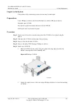
Page 118: ...red with the VCN500 Skill requirement weak current engineer Procedure Step 1 Make a note of the cable connection and ports of the VCN500 to be replaced using the marker Step 2 Shut down the VCN500 and disconnect the power plug Step 3 Remove all cables from the VCN500 Step 4 Remove the faulty VCN500 using a Phillips screwdriver Step 5 Install a new VCN500 1 Push the VCN500 into the cabinet along th...

Page 119: ...ACT indicator blinks green data transmission is normal If the hard disk active indicator blinks green the hard disk reads data properly End Follow up Procedure Dispose of the removed VCN500 that is confirmed faulty 6 3 10 Replacing a LAN Switch Prerequisites A LAN switch needs to be replaced A spare LAN switch of the same model is available and functional Impact on the System The monitoring system...

Page 120: ...move all cables connected to the LAN switch Step 4 Remove the screws securing the faulty LAN switch using a Phillips screwdriver and take out the faulty LAN switch Step 5 Install a new LAN switch Figure 6 31 Installing a LAN switch Step 6 Reconnect all cables Step 7 Connect the power plug of the LAN switch Step 8 Check that the new LAN switch is working properly If the PWR1 PWR2 and SYS indicators...

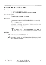
Page 121: ...at head screwdriver insulation tape marker Materials spare ECC500 collector Documents ECC500 collector port layout documents delivered with the ECC500 collector management system initial configuration table Skill requirement weak current engineer For the diagrams and tables see the initial configuration parameter manual for the solution in use For details about how to remove devices inside an ECC5...

Page 122: ...yright Huawei Technologies Co Ltd 114 Figure 6 32 Removing the faulty ECC500 collector Step 4 Install a new ECC500 collector in the same way and secure it using screws Figure 6 33 Installing the ECC500 collector Step 5 Connect cables based on the marks Step 6 Start the ECC500 collector and check that the new collector is working properly ...

Page 123: ...m The operation of the RH2288 system or devices connected to the server may be interrupted Preparations Tools Phillips screwdriver small sized flat head screwdriver ESD gloves marker Materials spare RH2288 server Documents documents delivered with the RH2288 server management system initial configuration table monitoring device layout diagram Skill requirement weak current engineer For the diagram...

Page 124: ...operly If power indicator of the server turns green the server is working properly Step 7 Configure the server by referring to the management system initial configuration table End Follow up Procedure Dispose of the removed RH2288 server that is confirmed faulty 6 3 13 Replacing Access Control Components 6 3 13 1 Replacing a Card Reader Prerequisites A card reader needs to be replaced A spare card...

Page 125: ...curing the card reader remove connectors of the card reader and take out the card reader Step 3 Replace the card reader and reinstall the terminal block Step 4 Reinstall the baffle plate and tighten screws Step 5 Configure the card reader by referring to the management system initial configuration table Step 6 Check that the new card reader is working properly The access card reader is working pro...

Page 126: ...s to be replaced A spare exit button of the same model is available and functional Impact on the System None Preparations Tools insulation tape Phillips screwdriver flat head screwdriver protective gloves Materials spare exit button Documents required none Skill requirement weak current engineer Procedure Step 1 Open the cover for the exit button remove the cables and remove the exit button to be ...

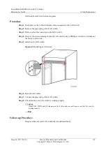
Page 127: ...button is working properly End Follow up Procedure Dispose of the removed exit button that is confirmed faulty 6 3 13 3 Replacing an Electronic Lock Prerequisites An electronic lock needs to be replaced A spare electronic lock of the same model is available functions properly Impact on the System None Preparations Tools Phillips screwdriver 3 mm hex key step ladder 2 m Materials spare electronic l...

Page 128: ...ght Huawei Technologies Co Ltd 120 Figure 6 37 Removing screws Step 2 Remove cables connected to the electronic lock Step 3 Use a 3 mm hex key to loosen screws from the baffle plate of the electronic lock as shown by 2 and 3 in Figure 6 37 Step 4 Replace the electronic lock with the spare one and connect cables Figure 6 38 Connecting cables ...

Page 129: ...s The emergency door release button needs to be replaced A spare emergency door release button of the same model is available and functional Impact on the System None Preparations Tools insulation tape step ladder 2 m Phillips screwdriver protective gloves Materials spare emergency door release button Documents required none Skill requirement weak current engineer Procedure Step 1 Remove the emerg...

Page 130: ... glass panel as shown by 2 and 3 in Figure 6 40 4 Tighten screws as shown by 4 in Figure 6 40 Figure 6 40 Installing the emergency door release button Step 3 Check that the new emergency door release button is working properly Remove the cover of the emergency door release button using a Phillips screwdriver press the button and rotate the door handle clockwise to open the container door If the do...

Page 131: ...l requirement weak current engineer For the diagrams and tables see the initial configuration parameter manual for the solution in use Procedure Step 1 Switch off the access controller circuit breaker in the PDB Step 2 Remove screws securing the fingerprint scanner and remove cables as shown by 1 2 and 3 in Figure 6 41 Figure 6 41 Replacing a fingerprint scanner Step 3 Remove the base plate of the...

Page 132: ...available and functional Impact on the System None Preparations Tools Phillips screwdriver small sized flat head screwdriver protective gloves Materials key to the access controller box spare access controller Documents documents delivered with the access controller power supply and distribution system diagram management system initial configuration table Skill requirement extra low voltage ELV en...

Page 133: ...set the device address for the access controller by following instructions in the management system initial configuration table Step 4 Install the new access controller and reconnect the terminal blocks and network cable Install terminals on the left and right of the access controller based on the mapping between cable labels and the silk screens on the access controller Step 5 Secure the access c...

Page 134: ... stops working during the replacement Preparations Tools protective gloves step ladder Phillips screwdriver Materials spare smoke detector Documents fire extinguishing device layout diagram standard Skill requirement fire engineer For the diagrams see the initial configuration parameter manual for the solution in use Before replacing the smoke detector inform the related administration department ...

Page 135: ...op in parallel remove the terminal resistor from the faulty smoke detector and connect the resistor to the new smoke detector when you replace the smoke detector Step 4 Remove the screws on the base using a Phillips screwdriver and remove the base Step 5 Install the new base to the same position and reconnect the cables Step 6 Hold the new smoke detector body align the smoke detector indicator wit...

Page 136: ...If the red indicator blinks once every 6s the smoke detector is working properly End Follow up Procedure Dispose of the removed smoke detector that is confirmed faulty 6 4 2 Replacing a Heat detector Standard Prerequisites A heat detector needs to be replaced A spare heat detector of the same model is available and functional Impact on the System The fire extinguishing system stops working during ...

Page 137: ... 2 Hold the heat detector and rotate it counterclockwise to remove it from the base Figure 6 45 Removing a heat detector Step 3 Remove cables from the base using a Phillips screwdriver As a terminal resistor is connected to the last heat detector in the loop in parallel remove the terminal resistor from the faulty heat detector and connect the resistor to the new heat detector when you replace the...

Page 138: ...once every 6s the heat detector is working properly End Follow up Procedure Dispose of the removed heat detector that is confirmed faulty 6 4 3 Replacing the Gas Release Indicator Standard Prerequisites A gas release indicator needs to be replaced A spare gas release indicator of the same model is available and functional Impact on the System The fire extinguishing system stops working during the ...

Page 139: ...n Figure 6 47 using a Phillips screwdriver and remove the panel Figure 6 47 Removing the screws Step 3 Remove the cables using a flat head screwdriver and label the cables Step 4 Remove the screws on the base using a Phillips screwdriver and remove the base Step 5 Install the new base in the same position Step 6 Reconnect cables in the same way Step 7 Secure the panel to the base Step 8 Switch on ...

Page 140: ...ose of the removed gas release indicator that is confirmed faulty 6 4 4 Replacing an Indoor Fire Alarm Horn Strobe Standard Prerequisites A fire alarm horn strobe needs to be replaced A spare fire alarm horn strobe of the same model is available and functional Impact on the System The fire extinguishing system stops working during the replacement Preparations Tools Phillips screwdriver flat head s...

Page 141: ...p 2 Pry open a seam at the top clip using a flat head screwdriver to separate the top cover from the base Figure 6 49 Removing a fire alarm horn strobe Step 3 Remove the two cables using a Phillips screwdriver When removing cables clearly label the cables with its corresponding terminal ports Step 4 Remove the screws on the base using a Phillips screwdriver and remove the base Step 5 Install the n...

Page 142: ... System The fire extinguishing system stops working during the replacement Preparations Tools Phillips screwdriver step ladder Materials spare horn strobe Documents fire extinguishing device layout diagram standard Skill requirement fire engineer For the diagrams see the initial configuration parameter manual for the solution in use Before replacing the horn strobe inform the related administrativ...

Page 143: ...s label the cables with its corresponding terminal ports for later connection Step 4 Remove screws from the horn strobe using a Phillips screwdriver and remove the base Step 5 Reconnect cables in the same way Figure 6 51 Connecting cables Connect the black wire to the leftmost binding post and connect the red wire to the middle binding post Step 6 Install the new horn strobe base in the same way a...

Page 144: ... The horn strobe should be activated End Follow up Procedure Dispose of the removed horn strobe that is confirmed faulty 6 4 6 Replacing a Fire Alarm Sounder Standard Prerequisites A fire alarm sounder needs to be replaced A spare fire alarm sounder of the same model is available and functional Impact on the System The fire extinguishing system stops working during the replacement Preparations Too...

Page 145: ...m the related administrative departments of the temporary downtime of the fire extinguishing system After the replacement inform the administration department that the system has become operational Procedure Step 1 Switch off the active and standby power supplies to the fire alarm control panel Step 2 Push the fire alarm sounder out of the base Figure 6 53 Removing a fire alarm sounder Step 3 Cut ...

Page 146: ... alarm sounder is working properly Unlock the fire alarm control panel and press ALARM BELL The fire alarm sounder should be activated End Follow up Procedure Dispose of the removed fire alarm sounder that is confirmed faulty 6 4 7 Replacing the Emergency Start Abort Switch Standard Prerequisites The emergency start abort switch needs to be replaced A spare emergency start abort switch of the same...

Page 147: ...alarm control panel Step 2 Use a Phillips screwdriver to remove the screws from the emergency start abort switch as shown in Figure 6 55 Figure 6 55 Removing the emergency start abort switch Step 3 Pry the cover of the emergency start abort switch from the base using a flat head screwdriver to separate them Step 4 Remove the cables using a flat head screwdriver and label the cables Step 5 Remove t...

Page 148: ...bort switch is working properly End Follow up Procedure Dispose of the removed emergency start abort switch that is confirmed faulty 6 4 8 Replacing Batteries for the Fire Alarm Control Panel Standard Prerequisites Fire alarm control panel batteries need to be replaced Spare fire alarm control panel batteries of the same model are available and functional Impact on the System None Preparations Too...

Page 149: ...Step 2 Use a Phillips screwdriver to remove the battery fixing plate Do not short circuit the positive and negative terminals during the operation Figure 6 57 Removing the fixing plate Step 3 Remove cables from the fire alarm control panel batteries and remove the batteries Step 4 Install the new batteries to the proper positions of the fire alarm control panel Step 5 Connect battery cables to the...

Page 150: ...nnecting battery cables Step 6 Use a Phillips screwdriver to secure the battery fixing plate Figure 6 59 Securing the fixing plate Step 7 Switch on the standby power supply to the fire alarm control panel Step 8 Check that the new batteries are working properly If the BATTERY FAULT indicator on the fire alarm control panel is off the new batteries are working properly End Follow up Procedure Dispo...

Page 151: ...rewdriver protective gloves adjustable wrench Materials spare fire cylinder sealing tape Documents fire extinguishing device layout diagram standard Skill requirement fire engineer For the diagrams see the initial configuration parameter manual for the solution in use Before replacing the fire cylinder inform the related administrative departments of the temporary downtime of the fire extinguishin...

Page 152: ...onnect the interconnection cables between the electromagnetic valve and the fire alarm control panel as shown in Figure 6 61 Disconnect cables from the electromagnetic valve as shown in Figure 6 62 Figure 6 61 Position of the interconnection cables Figure 6 62 Position of the cables to the solenoid valve Step 3 Disconnect the cables from the pressure announciator as shown in Figure 6 63 ...

Page 153: ... announciator Step 4 Remove the high pressure hose and adapter of the fire cylinder using an adjustable wrench as shown by 1 and 2 in Figure 6 64 Figure 6 64 Removing the high pressure hose and adapter Step 5 Loosen the straps on the fire cylinder Step 6 Move the fire cylinder out of the installation position Step 7 Move the fire cylinder to the installation position using a pallet truck and tight...

Page 154: ... or strike the fire cylinder during transportation or installation Assign sufficient people for transportation and installation if no auxiliary tool is available Keep the pressure gauge panel outwards so that people can view the reading Figure 6 65 Installing the fire cylinder straps 1 Fire cylinder straps Step 8 Connect cables of the electromagnetic valve to the interconnection terminal ...

Page 155: ...nnounciator Step 10 Reinstall the adapter and high pressure hose Step 11 Connect the cables between the electromagnetic valve and the fire alarm control panel Step 12 After installing the fire cylinder remove the safety pin on the fire cylinder Verify that the safety pin is removed after the system starts working properly otherwise the electromagnetic valve may fail to start and extinguishant may ...

Page 156: ...nce Guide 6 Parts Replacement Issue 02 2017 01 10 Huawei Proprietary and Confidential Copyright Huawei Technologies Co Ltd 148 Figure 6 67 Removing screws 2 Loosen the remaining three screws Figure 6 68 Positions of the screws 3 Remove the safety pin ...

Page 157: ...e cylinder has passed the air tightness test Tools and materials are ready All tools and materials except the camshaft device are provided by the charging station Extinguishant needs to be charged in the charging station Preparations Tools platform scale hose with a pressure tolerance greater than 2 5 MPa gate valve camshaft device pipe wrench adjustable wrench Materials extinguishant charging cyl...

Page 158: ...amshaft device Step 2 Move the fire cylinder onto the platform scale and record the weight reading Step 3 Connect the fire cylinder with the extinguishant charging cylinder and nitrogen cylinder Figure 6 71 Connecting cylinders Step 4 Set the counterweight to the fire cylinder weight reading plus the weight of fire extinguishant to be charged put on the handle for the camshaft rod and push the rod...

Page 159: ...40 ft Heptafluoropropane 48 kg Step 6 Open valve 3 to charge nitrogen into the fire cylinder until the pressure gauge reading reaches 2 5 MPa Then reset the camshaft to close the fire cylinder Step 7 Close valves 3 and 1 and remove the hose and camshaft device Step 8 Record the fire cylinder weight after the charging is complete and move the fire cylinder off the platform scale Step 9 Subtract the...

Page 160: ...ape gloves Phillips screwdriver Materials spare fire alarm control panel Documents delivered with the fire alarm control panel Skill requirement fire engineer Before replacing the fire alarm control panel inform the related administrative departments of the temporary downtime of the fire extinguishing system After the replacement inform the administration department that the system has become oper...

Page 161: ...es and cables outside of the box Keep labels on the cables intact so that cables can be connected to the correct terminals later Step 6 Remove the screws using a Phillips screwdriver and take out the faulty fire alarm control panel Step 7 Install the new fire alarm control panel in the same position Step 8 Put the corrugated pipes and cables back to the box and reconnect the cables according to la...

Page 162: ...er indicator is on and the alarm indicator is off the fire alarm control panel is working properly End Follow up Procedure Dispose of the removed fire alarm control panel that is confirmed faulty 6 4 12 Replacing an Emergency Light Standard Prerequisites An emergency light needs to be replaced A spare emergency light of the same model is available and functional Impact on the System None Preparati...

Page 163: ...y light tighten the screws on the box and plug the power cable Step 4 Press the TEST button on the emergency light panel to check whether the new emergency light is working properly If the new emergency light turns on it is working properly End Follow up Procedure Dispose of the removed emergency light that is confirmed faulty 6 5 Replacing Fire Extinguishing System Devices CE 6 5 1 Replacing a Sm...

Page 164: ...ent that the system has become operational Procedure Step 1 Disconnect the battery cables and switch off the input circuit breaker of the extinguishant control panel Step 2 Hold the smoke detector and rotate it counterclockwise to remove it from the base Figure 6 78 Removing a smoke sensor Step 3 Remove cables from the base using a Phillips screwdriver As a terminal resistor is connected to the la...

Page 165: ...same model is available and functional Impact on the System The fire extinguishing system stops working during the replacement Preparations Tools protective gloves step ladder Phillips screwdriver Materials spare heat detector Document fire extinguishing device layout diagram CE Skill requirement fire engineer For the diagrams see the initial configuration parameter manual for the solution in use ...

Page 166: ...ove the base Step 5 Install the new base to the same position and reconnect the cables Step 6 Insert the new heat detector into the base and rotate it clockwise until it locks in Step 7 Switch on the input circuit breaker of the extinguishant control panel and connect the cables to the battery Step 8 Check whether the new heat detector is working properly If the red indicator blinks once every 6s ...

Page 167: ... has become operational Procedure Step 1 Disconnect the battery cables and switch off the input circuit breaker of the extinguishant control panel Step 2 Loosen the screws securing the warning sign and its base using a Phillips screwdriver and remove the cover of the warning sign Figure 6 80 Removing screws Step 3 Remove the cables from the warning signs and label the cables Step 4 Remove the scre...

Page 168: ...spare horn strobe of the same model is available and functional Impact on the System The fire extinguishing system stops working during the replacement Preparations Tools Phillips screwdriver step ladder Materials spare horn strobe Documents fire extinguishing device layout diagram CE Skill requirement fire engineer For the diagrams see the initial configuration parameter manual for the solution i...

Page 169: ...a terminal resistor is connected to the last horn strobe in the loop in parallel remove the terminal resistor from the faulty horn strobe and connect the resistor to the new horn strobe when you replace the horn strobe Figure 6 82 Removing cables from the horn strobe Step 4 Remove screws from the horn strobe base using a Phillips screwdriver and remove the base Step 5 Install the new horn strobe i...

Page 170: ...red indicates that the horn strobe works properly 3 Reset the manual gas release button 4 Flip the key to Enable Control counterclockwise rightward Reset the extinguishant control panel by pressing Reset on it Then reset key to Enable Control clockwise leftward End Follow up Procedure Dispose of the removed horn strobe that is confirmed faulty 6 5 5 Replacing an External Horn Strobe CE Prerequisit...

Page 171: ...trobe inform the related administrative departments of the temporary downtime of the fire control system After the replacement inform the administration department that the system has become operational Procedure Step 1 Disconnect the battery cables and switch off the input circuit breaker of the extinguishant control panel Step 2 Remove screws from the horn strobe using a Phillips screwdriver and...

Page 172: ...stall the new base and cover Step 6 Switch on the input circuit breaker of the extinguishant control panel and connect the battery cables Step 7 Check that the new horn strobe is working properly 1 Disconnect the wiring terminals from the electrical actuator on the fire cylinder After the wiring terminals are disconnected from the electrical actuator the extinguishant control panel generates an al...

Page 173: ...ective gloves step ladder Materials spare horn strobe Documents fire extinguishing device layout diagram CE Skill requirement fire engineer For the diagrams see the initial configuration parameter manual for the solution in use Before replacing the fire alarm bell inform the related administrative departments of the temporary downtime of the fire extinguishing system After the replacement inform t...

Page 174: ... Install the new base in the same way connect the cables and install the cover Step 6 Switch on the input circuit breaker of the extinguishant control panel and connect the battery cables Step 7 Check whether the new fire alarm bell is working properly 1 Flip the key to Enable Control rightward and set the access level of the extinguishant control panel to 2 2 Press Silence Sound Alarm to start or...

Page 175: ...Documents fire extinguishing device layout diagram CE Skill requirement fire engineer For the diagrams see the initial configuration parameter manual for the solution in use Before replacing the extinguishant abort button inform the related administrative departments of the temporary downtime of the fire extinguishing system After the replacement inform the administration department that the syste...

Page 176: ...bort button and remove the panel of the extinguishant abort button Figure 6 87 Disconnecting cables from the extinguishant abort button As a resistor is installed on the loop of the extinguishant abort button remove the resistor and connect the resistor to the corresponding terminals of the new extinguishant abort button when you replace the extinguishant abort button Step 4 Remove the screws on t...

Page 177: ...ables to the correct terminals Step 7 Install the new extinguishant abort button panel in the same way Figure 6 89 Installing the extinguishant abort button Step 8 Switch on the input circuit breaker of the extinguishant control panel and connect the battery cables Step 9 Check whether the new extinguishant abort button is working properly 1 Disconnect the wiring terminals from the electrical actu...

Page 178: ...ard End Follow up Procedure Dispose of the removed the extinguishant abort button that is confirmed faulty 6 5 8 Replacing Batteries for the Extinguishant Control Panel CE Prerequisites Extinguishant control panel batteries need to be replaced Spare extinguishant control panel batteries of the same model are available and functional Impact on the System None Preparations Tools protective gloves st...

Page 179: ...emoved extinguishant control panel batteries that are confirmed faulty 6 5 9 Replacing a Fire Cylinder CE Prerequisites A fire cylinder needs to be replaced A spare fire cylinder of the same model is available and functional Impact on the System The fire extinguishing system stops working during the replacement Preparations Tools pipe wrench pallet truck Phillips screwdriver adjustable wrench prot...

Page 180: ...ker of the extinguishant control panel Step 2 Move the new fire cylinder using a pallet truck to a position adjacent to the container door Do not impact or strike the fire cylinder during transportation or installation Assign sufficient people for transportation and installation if no auxiliary tool is available Step 3 Disconnect the interconnection terminals on the electrical actuator from the ex...

Page 181: ...y fire cylinder from the installation position Step 8 Move the new fire cylinder to the installation position and tighten the straps Keep the pressure gauge panel outwards so that people can view the reading Step 9 Connect the hose to the pneumatic switch Wrap the threads with sealing tape to ensure air tightness Step 10 Connect the fire cylinder to the fire extinguishing pipeline Wrap the threads...

Page 182: ...hant release The electrical actuator ejector is 11 mm long before being pressed down and 7 mm long after being pressed down Figure 6 92 Operating the electrical actuator ejector 2 Align the electrical actuator and the container valve and tighten the actuator clockwise Step 12 Connect the interconnection terminals on the electrical actuator to the extinguishant control panel Step 13 Switch on the i...

Page 183: ...he extinguishant control panel inform the related administrative departments of the temporary downtime of the fire extinguishing system After the replacement inform the administration department that the system has become operational Procedure Step 1 Switch off the input circuit breaker on the extinguishant control panel Step 2 Remove the cables from the battery and take out the battery Step 3 Rem...

Page 184: ...t the batteries to the same position Step 9 Switch on the input circuit breaker of the extinguishant control panel and connect the battery cables Step 10 Check whether the new extinguishant control panel is working properly If the power indicator is on and the alarm indicator is off the fire control panel is working properly End Follow up Procedure Dispose of the removed extinguishant control pane...

Page 185: ...itial configuration parameter manual for the solution in use Procedure Step 1 Disconnect the power plug of the emergency light Figure 6 94 Removing the power plug Step 2 Remove the protective cover of the emergency light Step 3 Loosen the emergency panel using a flat head screwdriver and remove the panel Step 4 Remove screws from the emergency light base using a Phillips screwdriver and remove the...

Page 186: ...6 Replacing Batteries for the VESDA Power Box Prerequisites Batteries need to be replaced for the VESDA power box Spare VESDA power box batteries of the same model are available and functional Impact on the System None Preparations Tools Phillips screwdriver protective gloves Materials spare VESDA power box batteries Documents fire extinguishing device layout diagram standard Skill requirement fir...

Page 187: ...y power supply Step 3 Disconnect cables from the faulty VESDA batteries Step 4 Use a Phillips screwdriver to remove screws on the battery protective panel and remove the protective panel Step 5 Replace the batteries and connect battery cables Distinguish the positive and negative battery terminals when connecting battery cables Figure 6 97 Connecting battery cables Step 6 Reinstall the battery pro...

Page 188: ...awei Technologies Co Ltd 180 Figure 6 98 Installing the battery protective panel Step 7 Check whether the new VESDA batteries are working properly Turn on the standby power switch If the power fault indicator is off the batteries are working properly End Follow up Procedure Dispose of the removed VESDA power box batteries that are confirmed faulty ...

Page 189: ...Module1000 is faulty Context The FusionModule1000 power supply and distribution system supports the following power supply modes One mains supply and one DG Two mains supplies Two mains supplies and one DG Two mains supplies and two DGs Perform emergency operations based on the power supply mode used by the FusionModule1000 Procedure Step 1 Check whether the UPS is working properly Step 2 Check wh...

Page 190: ...er fails manually switch the ATS to the other mains or DG supply and check whether all devices are working properly Step 3 Monitor the system running until the mains supply is stored and the system is working properly End Follow up Procedure Analyze the cause of the fault and work out and record the preventive measures 7 2 Emergency Operations for Circuit Breaker Tripping Prerequisites A circuit b...

Page 191: ...ncy Operations for Battery Electrolyte Leakage Prerequisites The battery electrolyte leaks Procedure Step 1 Switch off the circuit breaker inside the BCB for the battery string where the electrolyte leakage occurs Ignore the alarm generated after the circuit breaker is switched off Step 2 Replace the battery that leaks electrolyte For details see 6 1 4 Replacing a UPS5000 E Battery Before the repl...

Page 192: ... Measure the actual ambient temperature using a thermometer Step 3 Check whether the actual temperature exceeds the designed normal range If no check whether the T H sensor is faulty and replace by following instructions in 6 3 1 Replacing a Polymer T H Sensor if it is faulty If yes go to Step 4 Step 4 Use a fan to blow cold air from other areas to the high temperature area to cool the area Step 5...

Page 193: ...Step 3 Step 3 Check whether the LAN switch in the FusionModule1000 is working properly If the LAN switch is faulty replace it by following instructions in 6 3 10 Replacing a LAN Switch If the LAN switch is powered on go to Step 4 Step 4 Check the signal cable connection between the LAN switch and the RH2288 server If any cable is not properly connected prepare and reconnect the cable and check whe...

Page 194: ... Open the door using the emergency door release button The emergency door release button is a one off component You can remove the glass cover of the emergency door release button and open the container door if you are not in an emergent situation Step 2 Enter the container and check the devices Step 3 Locate the cause why the container door cannot be opened after verifying that the devices are ru...

Page 195: ...ult and work out and record the preventive measures 7 9 Emergency Operations for Container Door Open Prerequisites A door open alarm is generated for the FusionModule1000 Procedure Step 1 Locate the door based on the alarm information Step 2 Enter the container verify that no device is lost and the system is working properly Then close the container door Step 3 Check whether the alarm is cleared I...

Page 196: ...ity and impact of the fire If both VESDA and fire alarms are generated handle the situation by following instructions in 7 11 Emergency Operations for a Single Fire Alarm Standard or 7 13 FIRE RELAY Emergency Operations CE You can enter the container when only a VESDA alarm is generated Step 3 Quickly check the alarm severity of the VESDA Step 4 Check whether there is smoke or something smoldering...

Page 197: ...ment system Step 2 Check the internal situation in the video surveillance system If the video surveillance system indicates that everything is normal go to Step 5 If onsite fire is confirmed go to Step 3 Step 3 Check whether extinguishant has been released If extinguishant is being released contact the local maintenance engineer or Huawei technical support to recharge the extinguishant after the f...

Page 198: ... the container If the fire alarm control panel reports a single fire alarm smoke alarm but the VESDA does not report any alarm go to 6 4 1 Replacing a Smoke Detector Standard If the fire alarm control panel reports a single fire alarm or a heat detector alarm but the management system does not report any overtemperature alarm go to 6 4 2 Replacing a Heat detector Standard If the fire alarm control...

Page 199: ...nd contact the personnel on duty or fire engineer Procedure Step 1 Locate the alarm or alarm area in the management system Step 2 Check the internal situation in the video surveillance system If the video surveillance system indicates that everything is normal go to Step 5 If onsite fire is confirmed go to Step 3 Step 3 Check whether extinguishant has been released If extinguishant is being releas...

Page 200: ...ou have any questions promptly contact Huawei technical support Figure 7 2 Position of the safety pin of an electromagnetic valve Step 5 Check whether there is an alarm on the fire alarm control panel outside the container Step 6 If the fire alarm control panel reports no double fire alarm check the cable connection from the fire alarm control panel to the management system If the cable connection...

Page 201: ...Locate the alarm area based on the alarm information Step 2 Check the internal situation in the video surveillance system If the video surveillance system indicates that everything is normal go to Step 5 If onsite fire is confirmed go to Step 3 Step 3 Check whether extinguishant has been released If extinguishant is being released contact the local maintenance engineer or Huawei technical support ...

Page 202: ...heck whether there is an alarm on the extinguishant control panel outside the container If the extinguishant control panel reports a FIRE RELAY alarm or smoke alarm but the VESDA does not report any alarm go to 6 5 1 Replacing a Smoke Detector CE If the extinguishant control panel reports a FIRE RELAY alarm or heat fire detector alarm but the management system does not report any overtemperature a...

Page 203: ...he personnel on duty or fire engineer Procedure Step 1 Locate the alarm area based on the alarm information Step 2 Check the internal situation in the video surveillance system If the video surveillance system indicates that everything is normal go to Step 5 If onsite fire is confirmed go to Step 3 Step 3 Check whether extinguishant has been released If extinguishant is being released contact the ...

Page 204: ...isks If you have any questions promptly contact Huawei technical support Figure 7 4 Position of the dowel of an electrical actuator Step 5 Go to the area with necessary tools and communications devices to check the cause of the fire alarm Step 6 Check whether there is an alarm on the extinguishant control panel outside the container Step 7 If the extinguishant control panel reports no LOCAL FIRE a...

Page 205: ...i Proprietary and Confidential Copyright Huawei Technologies Co Ltd 197 8 FusionModule1000 Emergency Exit Guide If an emergency occurs push open the nearest container door shown in the emergency exit diagram with force as shown in Figure 8 1 Then exit from the container immediately Figure 8 1 Opening the emergency exit door ...

Page 206: ...echnologies Co Ltd 198 9 Acronyms and Abbreviations A AC Alternating Current ACC Advanced Cooling Controller ATS automatic transfer switch C CAN control area network CE Conformite Europende D DDF digital distribution frame E ECC energy control center L LCD liquid crystal display M MDU monitor display module P PoE power over Ethernet PDF power distribution frame ...

Page 207: ...sue 02 2017 01 10 Huawei Proprietary and Confidential Copyright Huawei Technologies Co Ltd 199 PDU power distribution unit R rPDU rack power distribution unit S SIM subscriber identity module U UPS uninterruptible power system V VCN video cloud node VESDA very early smoke detection apparatus ...

Reviews: