7
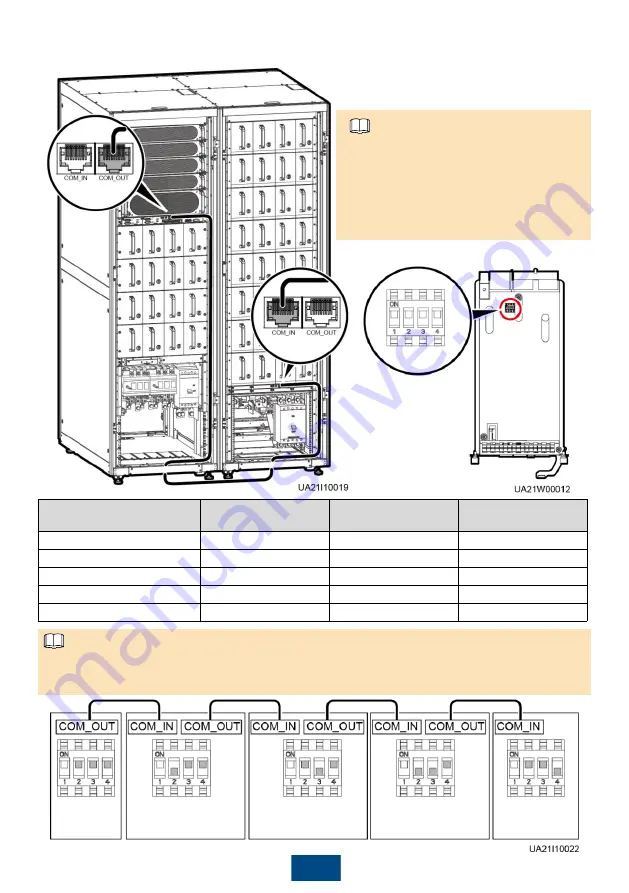
7. Set the DIP switches of CAN expansion card. Connect the communications cable between the
battery cabinet and the CAN expansion card in the UPS cabinet.
DIP1 to DIP4 represent the four
bits of the DIP switch. DIP2 is the
least significant bit and DIP4 is the
most significant bit. Ignore DIP1.
The figure and table below show
the position and status of DIP
switches.
Address of the CAN
Expansion Card
DIP2 Switch Status
DIP3 Switch Status
DIP4 Switch Status
UPS cabinet address
ON
ON
ON
Battery cabinet 1 address
OFF
ON
ON
Battery cabinet 2 address
ON
OFF
ON
Battery cabinet 3 address
OFF
OFF
ON
Battery cabinet 4 address
ON
ON
OFF
NOTE
UPS
Battery
cabinet 1
Battery
cabinet 2
Battery
cabinet 3
Battery
cabinet 4
This document describes how to connect cables between battery cabinets and UPS5000-E-
75K-BF as an example. A maximum of four battery cabinets can be connected in parallel. If
there is more than one battery cabinet, connect them as the figure below.
NOTE


