background image

2

Installation Process

Installation Tools

z

When an external antenna is used, 
connect the antenna to the BTS3701B 
before installing the BTS3701B. 

z

When the BTS3701B is installed on a 
wall, the integrated mode is 
recommended. 

z

The BTS3701B must be installed at least 
0.5 m (1'-7 11/16'') away from the 
interference sources such as power 
supply and at least 2 m (6'-6 3/4'') away 
from the high frequency radiation 
sources. 

The BTS3701B cannot be placed horizontally 
on a flat object, such as a table. 

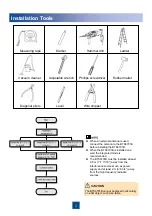
Measuring tape 

Marker

Hammer drill

Ladder

Vacuum cleaner

Adjustable wrench

Phillips screwdriver

Rubber mallet

Diagonal pliers

Level

Wire stripper

Summary of Contents for BTS3701B

Page 1: ...HUAWEI TECHNOLOGIES CO LTD Issue 01 Date 2010 03 20 BTS3701B V300R003 Installation Guide ...

Page 2: ...Never perform any high voltage AC operations or perform operations on a tower or a mast during a thunderstorm It can be lethally dangerous Any equipment must be grounded before it is connected to the power supply Ungrounded equipment can be lethally dangerous Never perform any hot line operation Strong RF signals are harmful to human health Ensure that the transmit antennas are shut down before an...

Page 3: ...mmended z The BTS3701B must be installed at least 0 5 m 1 7 11 16 away from the interference sources such as power supply and at least 2 m 6 6 3 4 away from the high frequency radiation sources The BTS3701B cannot be placed horizontally on a flat object such as a table Measuring tape Marker Hammer drill Ladder Vacuum cleaner Adjustable wrench Phillips screwdriver Rubber mallet Diagonal pliers Leve...

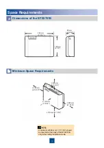
Page 4: ...nsions of the BTS3701B b A minimum of 500 mm 1 7 11 16 should be reserved at the back of the BTS3701B only in the ceiling installation mode 230 mm 9 1 16 165 mm 6 1 2 65 mm 2 9 16 300 mm 11 13 16 170 mm 6 11 16 100 mm 3 15 16 250 mm 9 13 16 250 mm 9 13 16 ...

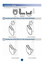
Page 5: ...ode a b Installing the BTS3701B on a Wall Integrated Mode Regular installation Reverse installation Regular installation Reverse installation BTS3701B Mounting bracket for the module Mounting bracket for the adapter Ceiling mounting bracket Transitional piece Adapter ...

Page 6: ... Mode c Regular installation Reverse installation Regular installation Reverse installation The requirements for the installation carrier are as follows Pole Angle steel U steel 20 mm 13 16 to 85 mm 3 3 8 20 mm 13 16 to 75 mm 2 15 16 20 mm 13 16 to 75 mm 2 15 16 20 mm 13 16 to 65 mm 2 9 16 20 mm 13 16 to 65 mm 2 9 16 ...

Page 7: ...made of concrete and can bear a weight of 323 6 N m 2864 10 lbf in Installing the BTS3701B on a Wall a Determining Installation Positions of the Mounting Brackets b Drilling Holes and Installing Expansion Bolts For the integrated installation mode determine only the installation position of the adapter 88 mm 3 7 16 200 mm 7 7 8 88 mm 3 7 16 24 mm 15 16 to 25 mm 1 ...

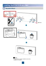
Page 8: ...7 Installing the BTS3701B on a Wall c Separated Mode 3 0 5 N m 26 55 4 43 lbf in M4 The procedures of regular installation and reverse installation are identical Installation procedure M3 5 20 ...

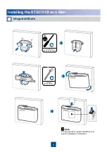
Page 9: ...8 Integrated Mode Installing the BTS3701B on a Wall d The procedures of regular installation and reverse installation are identical 3 0 5 N m 26 55 4 43 lbf in M4 10 N m 88 51 lbf in ...

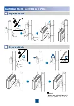
Page 10: ...01B on a Pole b Integrated Mode a Separated Mode 300 mm 11 13 16 The procedures of regular installation and reverse installation are identical 3 0 5 N m 26 55 4 43 lbf in M4 3 0 5 N m 26 55 4 43 lbf in M4 10 N m 88 51 lbf in ...

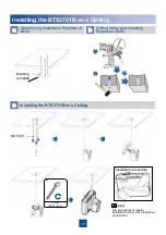
Page 11: ...eiling a Determining Installation Positions of Bolts b Drilling Holes and Installing Expansion Bolts c The procedures of regular installation and reverse installation are identical Installation procedure M3 5 20 Marking template 24 mm 15 16 to 25 mm 1 10 N m 88 51 lbf in ...

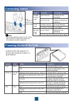
Page 12: ...ector to the AC power wiring bar to power on the BTS3701B An alarm is generated and the BTS3701B needs to be replaced On red The FE port is insecurely connected Off Data is being transmitted and received over the FE port Blinking at 4 Hz green on for 0 125s off for 0 125s The FE port is securely connected On Green LINK An alarm is generated Rectify the fault based on the reported alarm Blinking at...

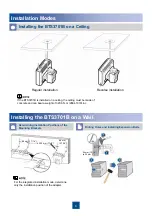
Page 13: ...ed on a pole fix the input power cable of the power adapter on the pole using a tie wrap z Before powering on the equipment ensure that the antenna of the BTS3701B is vertical Installing the BTS3701B on a Wall a Installing the BTS3701B on a Pole b c Separated Mode Integrated Mode Separated Mode Integrated Mode Installing the BTS3701B on a Ceiling ...

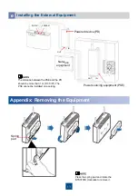
Page 14: ...te the BTS3701B clockwise to remove it Appendix Removing the Equipment Spring pad Installing the External Equipment e The distance between the PSE and the PD should be more than 1 m 3 3 3 8 The PSE cannot be installed on a ceiling Network equipment Power sourcing equipment PSE ...

Page 15: ...Huawei Technologies Co Ltd Administration Building Huawei Technologies Co Ltd Bantian Longgang District Shenzhen P R Zip code 518129 www huawei com ...

Reviews: