A-021
HYW3
Series Intelligent Universal Circuit Breaker
A
Primary power distribution
VII. Wiring Diagrams
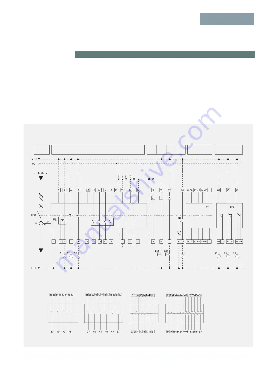
Secondary circuit wiring diagram
1) The circuit on the dotted line is wired by the user, which cannot be performed when the optional accessories are not customized.
2) The accessories such as intelligent controller, undervoltage release, shunt release, closing electromagnet and electric operating mechanism
shall be connected to different power supplies respectively when the voltages are different.
3) The undervoltage release shall be directly connected to the incoming line of the main circuit, with the highest working voltage not exceeding
its rated working voltage; when the working voltage of the main circuit exceeds its rated working voltage, a transformer is required to reduce it to
its rated working voltage before it can be used.
4) The three-position indication function of the drawer seat is only optional for the Draw-out circuit breaker.
5) When the working power supply of the intelligent controller is DC 110 V or DC 24 V, the ST power supply module (optional) shall be
connected first, and then the 1# and 2# intelligent controllers.
Main circuit
Intelligent controller
Undervo
ltage
release
Shunt
release
Closed
electrom
agnet
Electric
operating
mechanism
Auxiliary switch
Energy
storage
indication
Opening
indication
Closing
indication
To the incoming
side of the circuit
breaker
Draw-out-type three-
position indication
External
transformer
To the
main circuit
See the wiring type of
the auxiliary switch
Malfunction
indication
Connection
position
indication
Test
position
indication
Disconnection
position
indication
Wiring type of the auxiliary switch (default: Conversion 4 NO & 4 NC)
Conversion 4 NO & 4 NC
Conversion 6 NO & 6 NC
Independent 4 NO & 4 NC
Independent 6 NO & 6 NC
Wiring diagram of the secondary circuit of the Mic1.0, Mic2.0 Intelligent Controller


