2 Architecture and Introduction
Hardware Description
H20RN
-
2000.V2 Series Platforms
10
Beijing Huahuan Electronics Co., Ltd.
Version 1.3(Oct.2019)
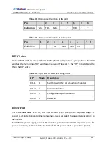
DIP
Definition
Remark
K3_7/K3_8
ON/ON: selects 75
Ω
in the 12
th
E1 channel
OFF/OFF: selects 120
Ω
in the 12
th
E1
channel
K4_1
/
K4_2
ON/ON: selects 75
Ω
in the 13
th
E1 channel
OFF/OFF: selects 120
Ω
in the 13
th
E1
channel
8-position DIP
switches of K4
control 13~16
E1 impedance
selections
K4_3/K4_4
ON/ON: selects 75
Ω
in the 14
th
E1 channel
OFF/OFF: selects 120
Ω
in the 14
th
E1
channel
K4_5/K4_6
ON/ON: selects 75
Ω
in the 15
th
E1 channel
OFF/OFF: selects 120
Ω
in the 15
th
E1
channel
K4_7/K4_8
ON/ON: selects 75
Ω
in the 16
th
E1 channel
OFF/OFF: selects 120
Ω
in the 16
th
E1
channel
STM-1 Port
The optical port of SC01QE uses LC/PC dual
-
fiber SFP optical module. Single
-
fiber SFP optical
module is also required to use the optical Ethernet. When using single
-
fiber transceiver
module, there is only one optical fiber port. The optical port supports LAS (laser automatic
shutdown) function.
External Clock Input/output Port
MX01/PXM01 card of H20RN
-
2000.V2 series platforms provides 1
-
channel of external clock
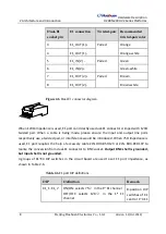
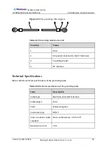
input\output port, supporting 2MHz, 2Mbit/s clock mode. It is marked with “BITS”, using RJ45
socket. RJ
-
45 connector diagram and pin definition are shown in Figure 2
Summary of Contents for H20RN-2000.V2 Series
Page 1: ...H20RN 2000 V2 Series IP MPLS Aggregation Platforms Hardware Description...
Page 4: ......
Page 10: ......


