lp-674 Rev. 5.7.18
4
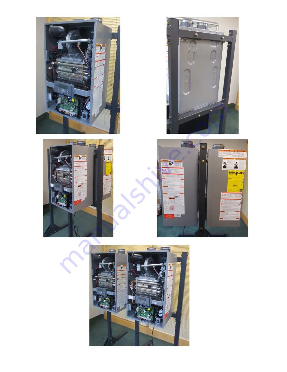
Figure 11 - Mounted Single Appliance
Figure 12 - Mounted Back to Back Appliances
Figure 13 - Mounted Side by Side Appliances (Possible with Extension Rack)
Page 1: ...omponents to the installation location Ensure you have all the components for the installation NOTE DO NOT lose these components Replacements ARE NOT included in this kit 2 Set the base feet in the installation location Verify finished installation clearances will meet the service clearance requirements of the appliance s to be mounted on the rack 3 Use a Phillips Head Screwdriver and eight 8 scre...
Page 2: ... Ensure you have all the components for the installation NOTE DO NOT lose these components Replacements ARE NOT included in this kit 2 Set the base foot in the installation location Verify finished installation clearances will meet the service clearance requirements of the appliance s to be mounted on the rack 3 Use a Phillips Head Screwdriver and four 4 screws to install the two 2 angle supports ...
Page 3: ...and in the installation location 2 Once properly positioned use a pencil to mark the drill holes for the lag screws expansion anchors Then move away the stand 3 Prepare to drill holes into the mounting surface either 4 thick minimum Wood Structural Member or 4 thick minimum Concrete Flooring Consult lag screw or expansion anchor manufacturer for predrill diameters 3 After taking appropriate precau...
Page 4: ...lp 674 Rev 5 7 18 4 Figure 11 Mounted Single Appliance Figure 12 Mounted Back to Back Appliances Figure 13 Mounted Side by Side Appliances Possible with Extension Rack ...