background image


HTC confidential   


© 2006, HTC CORPORATION. ALL RIGHTS RESERVED.        TOTAL 

58

   CONT.ON. 33  PAGE NO. 

32


I. 

Download OS image from SDO. 

http://htcscm10.htc.com.tw/SDO


II. 

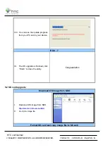
Un-zip the file and execute RUU 

program. 


III.  Follow instruction on your PC, 

complete check box and “NEXT” 

IV.  On process will show your device 

current ROM version, choose 

“UPDATE” 

Summary of Contents for Herald

Page 1: ...confidential 2006 HTC CORPORATION ALL RIGHTS RESERVED TOTAL 58 CONT ON 2 PAGE NO 1 Herald Service Manual HTC Proprietary Confidential Treatment Requested Rev A01 Nov 24 2006 HTC Corp Engineering Mobil...

Page 2: ...e Rev Date Contents Dept Revised App Dept Stage Per AX01 2006 10 16 First Draft PSE Jerry W Lin GSD DVT AX02 2006 11 16 Add Procedure PSE Jerry W Lin GSD PVT AX03 2006 11 17 Add description PSE Jerry...

Page 3: ...AM 27 4 1 LIST OF DIAGNOSTIC WINCE TEST ITEMS 27 4 2 TEST PROCEDURE 28 CHAPTER 5 SOFTWARE UPGRADE PRCEDURE 31 5 1 RUU RE FLASH UPGRADE UTILITY 31 5 2 SD CARD UPGRADE 34 CHAPTER 6 LEAKAGE CURRENT MEASU...

Page 4: ...Less than 168 g Main unit with battery pack Processor Chipset z TI OMAP 850 TI E Syren Memory z ROM 128 256MB for programs and users storage z RAM 64 MB DDR SDRAM LCD Module z 65K color TFT LCD with...

Page 5: ...side button z Camera capture left side button z Sliding Volume Up Down left side switch z 2 soft keys left and right z Five way navigation pad z 2 phone button Send End z 2 AP buttons Start OK z Rese...

Page 6: ...er WLAN Bluetooth z Compliant with V2 0 without EDR z Class 2 transmit power z Supported profiles Serial Port profile Object Push profile DUN profile Generic Object Exchange profile Headset profile He...

Page 7: ...tory z GCF certification z R TTE EMC EMI CEM Safety SAR z WiFi Certification z FCC z PTCRB z Bluetooth Qualification Body Certification z Microsoft Windows Mobile logo NTSL z USB Certification Accesso...

Page 8: ...4 WLAN AP For WiFi test 5 Micro SD Card with Diagnostic test program must be encoded by HTC For unit diagnostic test HTC design 6 128MB micro SD memory card must be encoded by HTC For unit ROM code t...

Page 9: ...3 DISASSEMBLING AND ASSEMBLING 3 1 Disassembling Tools needed for Assembling and Disassembling 1 Glove Lens Cleaning Tissue 2 Plastic type tweezers 3 Philip Screw Driver 000X40 4 Philip Screw Driver...

Page 10: ...HTC confidential 2006 HTC CORPORATION ALL RIGHTS RESERVED TOTAL 58 CONT ON 11 PAGE NO 10 Release rear cover lock by pressing to right Release battery Unfasten 4 screws located on rear of unit...

Page 11: ...58 CONT ON 12 PAGE NO 11 Release the antenna speaker module Disassembly C D parts Carefully insert flat plastic stick into the gap between C D part Be noticed this action should be performed very car...

Page 12: ...HTC confidential 2006 HTC CORPORATION ALL RIGHTS RESERVED TOTAL 58 CONT ON 13 PAGE NO 12 Release the housing Unfasten one screw which fix the MB Disassemble vibrator and release keyboard FPC...

Page 13: ...fidential 2006 HTC CORPORATION ALL RIGHTS RESERVED TOTAL 58 CONT ON 14 PAGE NO 13 Release board from its hook Lift up the main board release the LCM FPC and take out the MB Release Camera from its con...

Page 14: ...HTC confidential 2006 HTC CORPORATION ALL RIGHTS RESERVED TOTAL 58 CONT ON 15 PAGE NO 14 Unfasten 6 screws located on C D part rear housing Release keyboard Unfasten 4 screws as shown on picture...

Page 15: ...HTC confidential 2006 HTC CORPORATION ALL RIGHTS RESERVED TOTAL 58 CONT ON 16 PAGE NO 15 Upper part dis assembly Release receiver Unfasten two screws of RF board and two located on metal dome...

Page 16: ...HTC confidential 2006 HTC CORPORATION ALL RIGHTS RESERVED TOTAL 58 CONT ON 17 PAGE NO 16 Release LCM FPC separate RF board from LCM Release keypad from Bezel Disassemble display bottom COVER...

Page 17: ...HTC confidential 2006 HTC CORPORATION ALL RIGHTS RESERVED TOTAL 58 CONT ON 18 PAGE NO 17 Unfasten the screws Remove slider from bottom cover Remove slider from its hinge Disassembly process is done...

Page 18: ...HTC confidential 2006 HTC CORPORATION ALL RIGHTS RESERVED TOTAL 58 CONT ON 19 PAGE NO 18 3 2 Assembling Assemble slider hinge Align to its position Put Slider into bottom cover...

Page 19: ...ORPORATION ALL RIGHTS RESERVED TOTAL 58 CONT ON 20 PAGE NO 19 Assemble slider and fasten 6 screws 72H01701 00M Torque 1 1 0 1 kg cm Assemble LCM and connect its FPC into RF board Put the RF board FPC...

Page 20: ...ORPORATION ALL RIGHTS RESERVED TOTAL 58 CONT ON 21 PAGE NO 20 Maker sure FPC through the Slider Fasten 4 screws of RF board to display bottom cover 72H1715 00M Torque 0 8 0 1kg cm Assemble receiver pu...

Page 21: ...HTC confidential 2006 HTC CORPORATION ALL RIGHTS RESERVED TOTAL 58 CONT ON 22 PAGE NO 21 Put keypad on it Continue with assemble the bezel Starting from left and right then to the top...

Page 22: ...E NO 22 Fasten 4 screws on display bottom cover 72H01706 00M Torque 0 8 0 1kg cm Combine keyboard upper cover with display bezel keyboard upper cover combine with FPC Keypad Qwerty key Need Fixture to...

Page 23: ...Camera Pull out the slider and connect LCM FPC into MB Then stick LCM FPC with adhesive tape plus one tape to fix LCM FPC Assemble MB by inserting into ring put MB into keyboard upper cover and fasten...

Page 24: ...ION ALL RIGHTS RESERVED TOTAL 58 CONT ON 25 PAGE NO 24 Assemble vibrator into MB and put it in keyboard upper cover Then assemble MB into housing starting from its USB connector Check each button is a...

Page 25: ...06 HTC CORPORATION ALL RIGHTS RESERVED TOTAL 58 CONT ON 26 PAGE NO 25 Assemble antenna and speaker module starting from its right lower part Fasten 4 screws on rear side 72H01691H 00M Torque 1 2 0 1 k...

Page 26: ...HTC confidential 2006 HTC CORPORATION ALL RIGHTS RESERVED TOTAL 58 CONT ON 27 PAGE NO 26 Assemble battery cover and lock it into position Insert Stylus Assembly process is done...

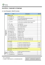
Page 27: ...Checksum Test ROM checksum test 10 Battery Test Battery info check 11 Vibrator Test Vibrator on test 12 Headset Play Test Headset out test 13 Speaker Play Test Speaker out test 14 Receiver Play Test...

Page 28: ...ton to start each of test items WinCE Test USB Test I Start up the Microsoft ActiveSync program in the PC II Insert USB cable and connect unit to desktop or laptop III The USB to PC icon is appears on...

Page 29: ...e Make this device Checkbox III Press Action key Jog ball to go next test pattern Bluetooth Test 2 I Tap Start Settings Connections Beam and select Receive all Checkbox II To create a file tap Start P...

Page 30: ...TOTAL 58 CONT ON 31 PAGE NO 30 I Tap icon Comm Manager on the Today screen and turn on WLAN II Select the hot spot or access point which searchable and appears on screen III Once the hot spot access...

Page 31: ...y For the master unit you could prepare it in the following ways Take one from Swap unit with the most up to date Rom Code Build one first by connecting to SDO for OS Upgrade Download via RUU HTC RMAI...

Page 32: ...AL 58 CONT ON 33 PAGE NO 32 I Download OS image from SDO http htcscm10 htc com tw SDO II Un zip the file and execute RUU program III Follow instruction on your PC complete check box and NEXT IV On pro...

Page 33: ...SERVED TOTAL 58 CONT ON 34 PAGE NO 33 V Confirm your ROM version and new update version then choose NEXT VI Click Next to proceed VII Read the information from pop up message and the OS update procedu...

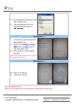
Page 34: ...update progress from your PC and in your device RUU 7 IX The OS upgrade is finished click Finish to close the utility Congratulation 5 2 SD card upgrade Download OS Image from SDO I Download OS image...

Page 35: ...ade 1 V Turn the device power off and insert Diagnostic SD card VI Press and hold Capture Comm MGR button and Reset button to entry Boot loader mode VII Press power key to start upgrade procedure Note...

Page 36: ...l leakage current on main board which caused high power consumption compare to GOOD main board 1 Requirement Power Supply Micro current Meter Current series JIG CABLE Battery JIG 1 Equipment need A Po...

Page 37: ...ty of power supply A and current meter B 4 Connect cable of fixture C to negative polarity of power supply A and current meter B Note black cable to power supply A and red cable to current meter B 5 S...

Page 38: ...58 CONT ON 39 PAGE NO 38 3 Connect cable C to positive polarity of power supply A and current meter B 4 Connect cable of fixture E to negative polarity of power supply A and current meter B 5 Setting...

Page 39: ...e current Choice Setting System Backlight Brightness Adjust brightness level to power save Current value must under 78mA if over it means M B failed please replace M B for repair 8 Switch OFF the unit...

Page 40: ...ONT ON 41 PAGE NO 40 I If current consumption test PASS when UUT in Flight and Sleep mode it means that the M B works normal II If current consumption test FAIL when UUT in Flight or Sleep mode it mea...

Page 41: ...ions Regarding functional inspection of CDIT please refer to CDIT SIP 7 1 Classes definition of inspective area 7 2 1 Class 1 area Class 1 area The front side of main unit involve all buttons and LED...

Page 42: ...n Accept criteria Level 1 Status of main unit assembly Defective assembly and deformed shape were nor allowed Minor 2 Gap between touch panel and bezel Gap between touch panel and bezel 0 7 mm Skip co...

Page 43: ...t allowed APP key hight 0 9mm Minor 2 Step inspection Description Accept criteria Level 1 Step between upper lower slid parts Step 0 50 mm Minor 2 Others between upper lower parts Step 0 40 mm Minor C...

Page 44: ...ing parts L 3mm W 0 254mm Minor 2 Burr W 0 25mm Max sharp edge is not acceptable Minor 4 Imprint mark Description Accept criteria Level Class 1 Class 2 Class 3 Cosmetic inspection refer to IS 3047 5 B...

Page 45: ...osmetic of Camera Symptom Standard Defect model Inner glass Accept Glue Out side glass Over to black area not accept Minor Inner glass W 0 25 mm and L 3 0 mm N 1 Should not affect to picture quality L...

Page 46: ...caused the power button fallen off 11 Both item 9 10 MB replacement is necessary unless you are authorized to do board level repair 12 If Charge light is red when plug in AC adapter it means the main...

Page 47: ...tion of LCM FPC whether is properly connected 2 Try with another LCM 3 Try with another Rigid Flex board 4 Try with another Main Board 5 Replace LCM if necessary 6 Replace rigid Flex board if necessar...

Page 48: ...nector on the unit whether it is physically damaged 4 Replace Main Board if necessary 5 Once the defective part has been identified verify it again with the defective part whether the symptom could be...

Page 49: ...apter and see if it takes charge Also check AC Adapter condition 3 Check whether AC Adapter is functioning properly 4 Check whether the condition of Battery Charging status is correct 5 Dismantle the...

Page 50: ...whether the Speaker is properly installed Orientation 4 Make sure the connection point between MB and Speaker is free from contamination or dust 5 Replace Speaker if necessary 6 Replace Main Board if...

Page 51: ...HTC confidential 2006 HTC CORPORATION ALL RIGHTS RESERVED TOTAL 58 CONT ON 52 PAGE NO 51 CHAPTER 9 GENERIC SPARE PART LIST 9 1 SPL for Repair...

Page 52: ...HTC confidential 2006 HTC CORPORATION ALL RIGHTS RESERVED TOTAL 58 CONT ON 53 PAGE NO 52 9 2 Board Level SW 7 CON1 CON2 PCON1 CON6 AMIC1 SW 3 SW 1 CON9 CON3 SW 4 CON5 ACON1 SW 5 SW 6...

Page 53: ...TC CORPORATION ALL RIGHTS RESERVED TOTAL 58 CONT ON 54 PAGE NO 53 APPENDIX A Generic Labeling Plan A1 Agency label W WiFi HTC P N 77H00385 00M Size 41 8 X 62 1mm The brand name is shown on Bezel HTC P...

Page 54: ...fidential 2006 HTC CORPORATION ALL RIGHTS RESERVED TOTAL 58 CONT ON 55 PAGE NO 54 A2 Agency label W O WiFi HTC P N 77H00385 04M Size 41 8 X 62 1mm The brand name is shown on Bezel HTC P N Countries su...

Page 55: ...5 104 7 TX Phase Peak Error 5 975 104 8 TX Frequency Error 5 975 104 9 TX Phase RMS Error 5 42 104 10 TX Phase Peak Error 5 42 104 11 TX Frequency Error 5 42 104 12 TX Phase RMS Error 5 124 104 13 TX...

Page 56: ...0 661 104 3 Fast Bit Error Rate 0 810 104 PCS 1900 Transmitter Test 4 TX Phase RMS Error 0 512 104 5 TX Phase Peak Error 0 512 104 6 TX Frequency Error 0 512 104 7 TX Phase RMS Error 0 661 104 8 TX Ph...

Page 57: ...128 104 6 TX Frequency Error 5 128 104 7 TX Phase RMS Error 5 189 104 8 TX Phase Peak Error 5 189 104 9 TX Frequency Error 5 189 104 10 TX Phase RMS Error 5 251 104 11 TX Phase Peak Error 5 251 104 12...

Page 58: ...HTC confidential 2006 HTC CORPORATION ALL RIGHTS RESERVED TOTAL 58 CONT ON F PAGE NO 58...

Reviews: