HLogic Security Technology Co., Ltd
www. hstfire .com
Document Ref: M1215-04
Issue: 5.5
01/2017
Note:
maximum wiring resistance is 50 ohms.
Note
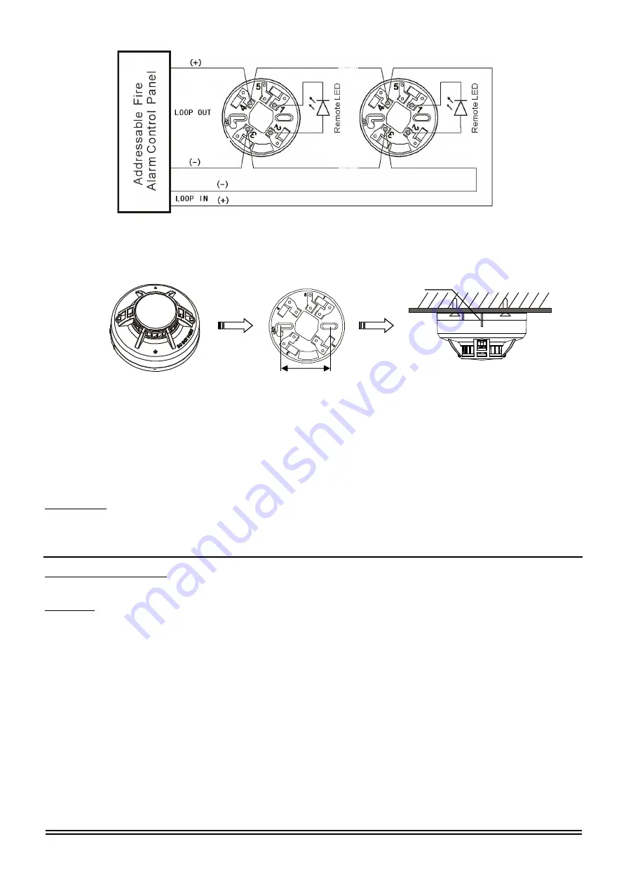
: During the installation, Make the rib of the detector align with the rib on the base until it drops into place.(see
figure 3)
Note
: Dust covers are an effective way to limit the entry of dust into smoke detector sensing chambers. However, they
may not completely prevent airborne dust particles from entering the detector. Therefore, We recommends the removal of
detectors before beginning construction or other dust producing activity.
Be sure to remove the dust covers from any sensors that were left in place during construction as part of returning the
system to service.
Remote LED
The remote indicator is connected between terminals 1 and 4 as showing Figure 2. The remote indicator must be current
limited to 20mA @24V. Maximum. Not limiting current could result in damage to the detector or cause a no alarm
condition.
Tamper-Resistance
The detector include a tamper-resistant capability that prevents their removal from the bracket without the use of a tool.
Testing
Before testing, notify the proper authorities that the smoke detector system is undergoing maintenance and will
temporarily be out of service. Disable the zone or system undergoing maintenance to prevent unwanted alarms. Detectors
must be tested after installation and as part of periodic maintenance.
NOTE: Before testing the detector, check to ensure the LEDs blink. If they do not, the detector has lost power (check the
wiring), it is defective (return it for repair), or the detector sensitivity is outside the listed limits.
The sensor can be tested in the following ways:
Smoke Entry test: Aerosol Generator (Gemini 501)
The GEMINI model 501 aerosol generator can be used for smoke entry testing. Set the generator to represent 4%/ft to
5%/ft obscuration as described in the GEMINI 501 manual. Using the bowl shaped applicator, apply aerosol until the
panel alarms.
A sensor that fails any of these tests should be cleaned as described under CLEANING, and retested. If the sensor fails
after cleaning, it must be replaced.
When testing is complete, restore the system to normal operation and notify the proper authorities that the system is back
in operation.
Figure 2. Typical wiring diagram
60mm
Figure 3. Install the detector
Rib
Detector
Base
Installed


