


17
7.
PWM SIGNAL CONTROL MODE
7.1 Control and Signal
1)
Control Principle
HST EPS series model pump is controlled by modulated LV PWM (Pulse Width Modulation)
digital signal, which means that the variance of velocity depends on the external input signal.
The variance of velocity is one of the functions of input control.
2)
Digital LV PWM (Pulse Width Modulation) Signal
Design frequency scope of square wave PWM signal: 100Hz
~
2000Hz; PWM input signal
(PWM IN) is used to give velocity commands, and adjusts the velocity commands through
adjusting PWM duty cycle. PWM output signal (PWM OUT) is the feedback signal of the
pump, and the PWM frequency is fixed at 75Hz±5%
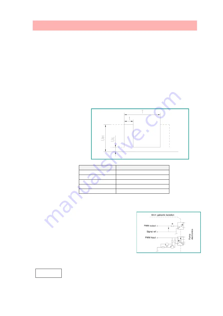
3)
Duty Cycle
(
d%
)
d
%
=t/T
For example
:
T = 2 ms
(
500Hz
)
t = 0.6 ms
d%=100×0.6/2=30
U = 7
~
15V ich
U ≤ 1V iL
I ≤ 10mA
Code
Descriptions
T
Cycle
D
Duty Cycle
UiH
Input High Voltage
UiL
Input Low Voltage
IiH
Input Current
7.2 Interface
The pump is controlled by external electrical
elements and components through interfaces. The
interfaces convert external signals into signals that
can be recognized by microprocessor in the pump.
In addition, when the pump is supplied with 230V
voltage, the interfaces can ensure that users will not
be at risk of high voltage electric shock when
contacting the signal cable.
“
Signal Ref” is a reference earthing, and it is not connected to protective earthing
Note
Summary of Contents for EPS Series
Page 2: ...2 TABLE OF CONTENTS ...
Page 4: ...4 DIMENSIONS TECHNICAL DATA ...
Page 24: ...24 EPS XX 5 series EPS XX 6 series Performance curve Performance curve ...
Page 25: ...25 EPS XX 7 Serie EPS XX 7 5 Serie ...
Page 29: ...29 FAULTCHECKLIST ...
Page 31: ...31 ...