background image

2


0912

FA 490.1

Contents

Proper use, warranty .................................................................................................................3

2 Safety 

instructions 

.....................................................................................................................3

3 Overview 

...................................................................................................................................4

4 Dimensions 

...............................................................................................................................5

5 Transportation, 

installation 

........................................................................................................6

Operating and display elements on the keypad ........................................................................7

Start-up and inspecting the safety devices ...............................................................................8

8 Malfunctions 

............................................................................................................................10

Maintenance and care ............................................................................................................10

10 Technical 

data 

.........................................................................................................................13

11  Electric wiring diagrams ..........................................................................................................14

HSM of America LLC

1075 Andrew Drive
Suite C
West Chester, PA 19380
USA

Phone: 

001 610 918 4894

Fax: 

001 610 918 4899

E-mail: [email protected]
www.hsmofamerica.com

HSM (UK) Ltd.

14, Attwood Road / Zone 1
Burntwood Business Park
Burntwood
Staffordshire
WS7 3GJ
United Kingdom

Phone: 

+44 (0) 1543 272 480

Fax: 

+44 (0) 1543 272 080

E-mail: [email protected]
www.hsmuk.co.uk

HSM GmbH + Co. KG

Austrasse 1-9
88699 Frickingen / Germany

Tel.   +49 7554 21 00-0
Fax.  +49 7554 2100 160
[email protected]
www.hsm.eu

Summary of Contents for FA 490.1

Page 1: ...HSM FA 490 1 english Keep this instruction for future use 1 612 999 121 0912 OPERATING INSTRUCTIONS PAPER SHREDDER ...

Page 2: ...ectric wiring diagrams 14 HSM of America LLC 1075 Andrew Drive Suite C West Chester PA 19380 USA Phone 001 610 918 4894 Fax 001 610 918 4899 E mail email hsmofamerica com www hsmofamerica com HSM UK Ltd 14 Attwood Road Zone 1 Burntwood Business Park Burntwood Staffordshire WS7 3GJ United Kingdom Phone 44 0 1543 272 480 Fax 44 0 1543 272 080 E mail info hsmuk co uk www hsmuk co uk HSM GmbH Co KG Au...

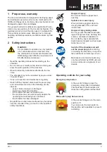
Page 3: ...rties 2 Safety instructions Caution It is prohibited to operate one only machine of a combination version machine Only the combination of document shredder and HSM baling press fulfils the requirements of EN 294 Safety clearances Read the operating manual before starting up the shredder Do not remove or modify safety devices which guar antee the safe operation of the machine Observe all safety ins...

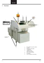
Page 4: ...6 7 HSM GmbH Co KG Austrasse 1 9 88699 Frickingen Germany 4 3 2 5 8 1 Main switch only solo version 2 Keypad 3 Emergency stop button 4 Loading tray 5 Intake conveyor paper feed opening 6 Braking swivel castors 7 Nameplate 8 Oiler on particle cut machines 1 ...

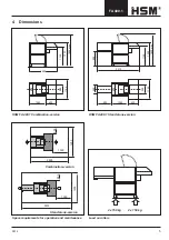
Page 5: ...d on rollers HSM FA 490 1 Combination version HSM FA 490 1 Stand alone version Combination version Stand alone version 2 x 150 kg 2 x 150 kg 800 2570 1895 max 1350 1125 1690 1895 max 1350 1125 1060 630 500 1155 800 800 560 880 1060 630 500 1155 3570 500 1000 1255 1000 500 1255 2690 ...

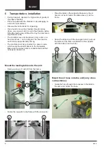
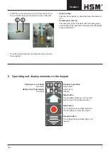
Page 6: ...ch roller is approximately 150 kg The machine must be connected to a power source which meets the specifications on the nameplate Make sure the power cable is unobstructed and that nobody can tread on it Mount the loading table onto the unit Remove screws 1 and 2 from the frame Fasten the supports to the frame with the screws 2 Place the table on the supports Make sure the oil hose is not bent Fas...

Page 7: ...e shredder with the baling press is described in the operator s manual of the Shredder press combination Ready for operation Green LED Light has no function Start button The shredder switches on The feed belt moves in the intake direction Stop button The cutting block and feed belt stop The shredder is in standby mode Reverse button The cutting block and feed belt run in reverse Paper jam or overl...

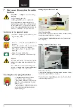
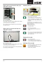
Page 8: ...he feed belt can run in reverse if the phase wires in the power plug are incorrectly con nected Turn off the main switch immediately and pull out the power plug Have an electrician change two of the three phase wires Checking the emergency stop button Press the emergency stop button while the machine is running The shredder must switch off immedi ately The cutting block and the feed belt must stop...

Page 9: ... button The cutting block and feed belt start up Place the material to be shredded on the loading tray and then place batches on the feed belt If material that is not supposed to be shred ded is mistakenly placed onto the belt never attempt to pull it out Press the stop button The drive stops Press the reverse button The cutting block and feed belt run in reverse You can now remove the material fr...

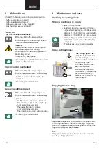
Page 10: ...on The inspection door is closed only stand alone version The protective flap is in vertical position Press the green start button Paper dust and particles accumulate in the paper shred der during operation To facilitate cleaning the ground plate of the paper shredder was designed as a tray This tray must be emptied every week Note The paper shredder cannot be switched on unless the dust tray is f...

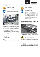
Page 11: ...the drive chains and cogs twice yearly Switch off the shredder Pull out the power plug Remove the left and right side covers Grease the cogs and the drive chains from the motor to the cutting apparatus the cut ting block to the feed belt and the cutting block to the regulating roller Recommended lubricating grease K2K in accordance with DIN 51502 DIN 51825 Reinstall the covers Maintenance work on ...

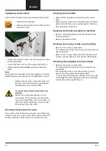
Page 12: ... feed belt can become worn after long periods of use If you can see the fabric inlay in the belt it must be replaced Please notify our customer service 1 2 3 Cleaning the shredder Switch off the shredder and disconnect the mains plug When cleaning only use a soft cloth and a mild soap water solution Never use scouring agents cleaning fluid petroleum or thinners Cleaning the tensioning station mont...

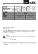
Page 13: ...irector Machine type inspection for compliance with the requirements of the EC Machine Directive was carried out by the Administration Inspection Authority Committee of Experts Subject Area Office Machines and Devices on the premises of TÜV Rheinland Product Safety GmbH Am Grauen Stein 51105 Köln Germany This inspection authority is the authority responsible in accordance with the EC Machine Direc...

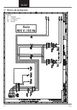
Page 14: ...14 0912 FA 490 1 Solo 400 V 11 Electric wiring diagrams Solo 400 V 50 Hz Legend AV Shredder S in switch cabinet MA on machine BF Keypad ...

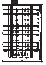
Page 15: ...0912 15 FA 490 1 Solo 400 V ...

Page 16: ...16 0912 FA 490 1 Solo 400 V ...

Page 17: ...0912 17 FA 490 1 Kombi 400 V Combination 400 V 50 Hz ...

Page 18: ...18 0912 FA 490 1 Kombi 400 V ...

Page 19: ...0912 19 FA 490 1 Kombi 400 V ...

Page 20: ...20 0912 FA 490 1 Kombi 400 V ...

Reviews: