HRS EM30MSD Series Quick Start Manual Download Page 4


HIROSE ELECTRIC CO.,LTD.


ETAD-C0320-00


4

 /


FORM HC0011-9-2 


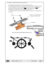
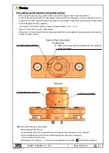
(5) Attaching the plug 


As a safety precaution, do not attach the plug until the electric lines have been completely attached. 

In addition, make sure that the power supply has been turned off and there are no hot-swaps in line   
with the service plug. 
 

To ensure that the plug does not unlock from vibrations or other movements, always make sure that   
the plug has been tightly locked in place. As shown in the reference image below, grasp the plug by   
the top handle section tightly to easily lock and unlock the plug. 

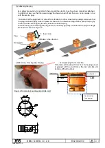
To make locking and unlocking the plug easier, an auxiliary grip may be added to the plug to enlarge   
the handle as shown in figure 2 


Reference

How to grasp the plug

                ・

Avoid grasping the lock section. 


If the lock section (about 15mm from the housing panel) 
is  grasped  with  too  much  force,  the  lock  will  stick  and 
become difficult to unlock. 


Figure 2: Sample lock auxiliary grip [Units: mm] 


Rotate in the direction 

of the arrow 


  Insert plug 


Plug 

Receptacle 


Handle section 

Grasp here


Lock section 

15mm


Summary of Contents for EM30MSD Series

Page 1: ...atic Tool Product description Product Name Product Code Comments Main unit CM 105 CL901 0005 4 00 Applicator AP105 GT8E 2022S CL901 5144 8 00 For GT8E 2022SCF AP105 GT8B 2428S CL901 5172 3 00 For GT8B 2428SCF Hand Tool Product description Product Name Product Code Comments Hand Tool HT 304 GT8E 2022S CL781 0042 6 00 For GT8E 2022SC 3 Installation 1 Installing the two small O rings to the main rece...

Page 2: ...the receptacle housing panel are shown in figure 1 below Roughness on the panel surface indicated by for water sealing must be When tightening the bolts apply a torque of approximately 6 to 6 5N m To prevent the bolts from loosening it is recommended to apply Locktie 243 or a similar product to the bolt area Figure 1 Recommended panel dimensions units mm Bolts Panel recommended panel Thickness t 2...

Page 3: ...ely 6 to 6 5N m To prevent the bolts from loosening it is recommended to apply Locktie 243 or a similar product to the bolt area Before the bolts have been tightened the female terminal of the receptacle will be loose and will move slightly However after the bolts have been tightened if the female terminal is still loose ensure that the crevice is less than 3mm so that nothing can fit in between a...

Page 4: ...y locked in place As shown in the reference image below grasp the plug by the top handle section tightly to easily lock and unlock the plug To make locking and unlocking the plug easier an auxiliary grip may be added to the plug to enlarge the handle as shown in figure 2 Reference How to grasp the plug Avoid grasping the lock section If the lock section about 15mm from the housing panel is grasped...

Page 5: ...the power source when using the service plug Because electric currents could be present do not touch the electric line terminals A and B in Table 1 while the power source is turned on When working near water make sure that water has not entered the receptacle opening after removing the plug If the plug is reattached while there is moisture in the receptacle opening there is a chance of electric sh...

Page 6: ...e 3 shows the plug when fully locked If the plug is not fully locked it can become separated from the receptacle during operation and present a danger of electric shock Figure 3 Plug in lock position Top down view Side view How to tell if the plug is fully locked When viewing from the top 1 The HRS symbol on the plug will rotate 90 degrees from its position when inserted 2 The receptacle lock symb...

Page 7: ...Directions Less than 3N m Use caution as these values may differ depending on the nature of the power lines being used 2 Mounting the power lines If the power lines are too long the weight of the lines is too much or vibrations from the operation environment cause an excessive load on the terminals deformation or damage to the circular connecting terminals can occur To prevent this it is highly re...

Reviews: