background image

Ham Radio Solutions

CW Hotline

Assembly Manual

Version 0.5 1-20-2022

The Ham Radio Solutions CW Hotline is a fairly simple construction project that can usually be built in
about two hours. You will need a low wattage pencil-type soldering iron with a small tip, some thin
solder, a pair of diagonal cutters and a Phillips head screwdriver. Desoldering braid may be required
to correct soldering mistakes. Be sure to wear eye protection when soldering and cutting leads.

Most parts, except for a few at the end, should be inserted into the side of the PCB with the jack
silkscreens J1, J2, J6.  Unless otherwise indicated, parts should be flush with the PCB. After
inserting, turn the board over and solder the leads to the pads on the other side. It is often helpful to
just solder one lead, then ensure the component is correctly positioned before soldering the
remaining leads. Be sure to only solder the correct pads, and do not let any solder touch any other
pad or trace. Trim any excess leads with diagonal cutters after soldering each batch of components.
The checklist will be useful to ensure all components are properly assembled.

Build slowly and follow the instructions. Use the images to confirm component placement.  CW
Hotline may be built with a straight key, Iambic paddles, or neither.  It is recommended to drill the
case first, then use the case to aid in placing some components on the PCB.
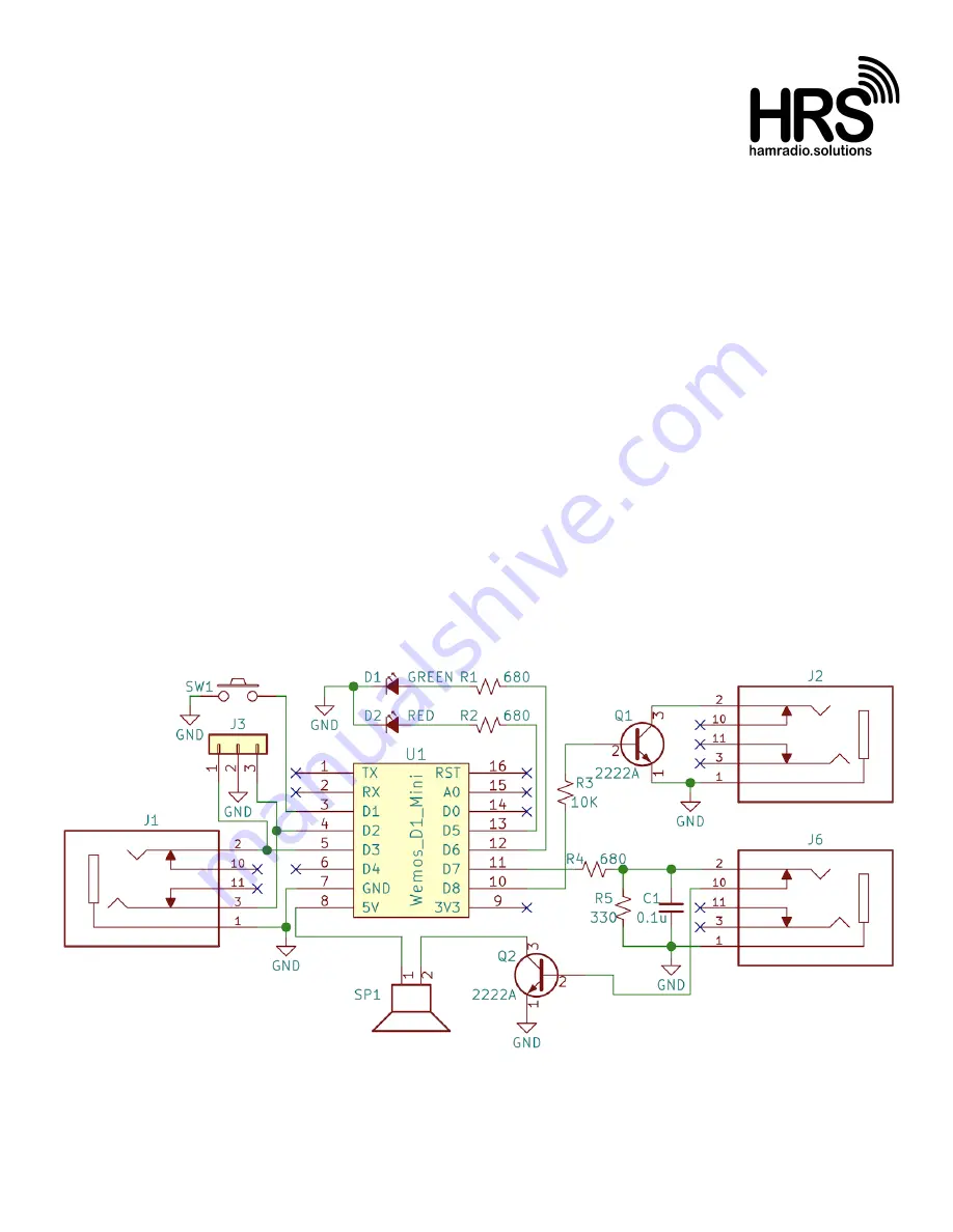
Schematic

Summary of Contents for CW Hotline

Page 1: ...wise indicated parts should be flush with the PCB After inserting turn the board over and solder the leads to the pads on the other side It is often helpful to just solder one lead then ensure the component is correctly positioned before soldering the remaining leads Be sure to only solder the correct pads and do not let any solder touch any other pad or trace Trim any excess leads with diagonal c...

Page 2: ...he rectangular hole on the other short case side along the dotted lines Remove the template and tape The template will help to reference hole sizes Drill out all 15 holes with the 5 64 2mm drill bit Enlarge the LED button and side holes with the 3mm drill bit Do not enlarge the 7 speaker holes Enlarge the button and side holes with a 5 32 4mm drill bit Do not enlarge the other top holes Enlarge th...

Page 3: ...d then solder the remaining pins Insert the blue ESP8266 PCB onto the long sides of the previous header posts being sure to match the silk screen orientation with the reset button nearest the upper left corner Solder only two diagonally opposite pins to the hole on the top face of the blue ESP8266 PCB and verify the board is flush Solder the remaining pins Do not trim the remaining exposed posts I...

Page 4: ...center of the PCB arm and lightly secure with a nut Insert the PCB arm onto the main PCB on the ESP8266 side through the 2 first screws with the third screw through the PCB hole marked GND Secure to the first 2 screws with 2 nuts Add the final nut to the third screw on the LED side of the PCB This screw should be rigidly secured to the main PCB and the screw head should only make contact with the ...

Page 5: ...e paddle arms tabs into the main PCB on the jack side Solder just one corner of one of the arm tabs on the LED side of the main PCB ensuring the arm is parallel with but doesn t contact the main PCB except at the soldering pad Once it is in position solder the rest of the tab Solder the other arm in a similar manner Install the washer to the screw and secure with a nut This washer will be the cont...

Reviews: