


MAINTENANCE
3-7
VALVE CLEARANCE CHECK/
ADJUSTMENT
Remove the four flange bolts (1) and the each valve
cover (2).
Remove the fan cover protector or screen grid (page 5-
2).
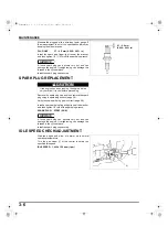
Disconnect the spark plug caps (3) from the spark
plugs.
Set the piston of the No.1 cylinder at the top dead
center of the cylinder compression stroke (both valves
fully closed) by rotating the flywheel (1) clockwise
slowly. When the No.1 piston is at the top dead center
of the compression stroke, the “T” mark (2) on the
cooling fan will align with the right side alignment mark
(3) on the fan cover.
If the exhaust valve is opened, rotate the flywheel and
align the “T” mark on the cooling fan with the alignment
mark on the fan cover again.
Insert a thickness gauge between the valve rocker arm
(1) and valve stem (2) to measure the valve clearance.
Set the piston of the No.2 cylinder at the top dead
center of the cylinder compression stroke (both valves
fully closed) by rotating the flywheel (1) 270 degrees
clockwise slowly. When the No.2 piston is at the top
dead center of the compression stroke, the “T” mark (2)
on the cooling fan will align with the left side alignment
mark (3) on the fan cover.
Insert a thickness gauge between the valve rocker arm
and valve stem to measure the valve clearance.
If adjustment is necessary, proceed as follows.
(2)
(1)
(3)
(2)
(1)
(3)
VALVE CLEARANCE:
IN: 0.08 ± 0.02 mm
EX: 0.10 ± 0.02 mm
(2)
(1)
VALVE CLEARANCE:
IN: 0.08 ± 0.02 mm
EX: 0.10 ± 0.02 mm
(2)
(1)
(3)
270°
62Z6P000.book 7 ページ 2009年7月9日 木曜日 午後1時35分


