Thermal Transfer Overprinter
FC53-Li/FC53-Lc/FC53-Ri/FC53-Rc
User Manual
Page 1: ...Thermal Transfer Overprinter FC53 Li FC53 Lc FC53 Ri FC53 Rc User Manual...
Page 2: ...he Ribbon Cassette 29 3 5 Load or Replace the Ribbon 30 3 5 1 Remove Waste Ribbon from the Waste Take up Core 30 3 5 2 Load a New Ribbon 31 3 6 1 Reconnect a Broken Ribbon 32 3 6 2 Ribbon Cassette Str...
Page 3: ...ar Monthly Checks 71 5 2 3 Maintaining the Print Head 71 5 3 Cleaning the Print Head 72 5 4 Replace Print Head 73 5 4 1 Remove the Damaged Print Head 73 6 INTERFACE FUNCTION DEFINITION SIGNAL FUNCTION...
Page 4: ...rfectly with the outlet do not plug in Be sure to use only standardized multi outlets 2 You must use the supplied adapter It is dangerous to use other adapters 3 Do not pull the cable to unplug This c...
Page 5: ...damage to the printer control circuit Never carry out maintenance or repair work yourself Always contact a qualified service Technician Keep this User Manual in a place which is easily accessible at a...
Page 6: ...cle them responsibly to promote the sustained reuse of material resources Household users should contact either the retailer where they purchased this product or their local government office for deta...
Page 7: ...d durable Control Panel Color touch screen panel with friendly UI interface Automatic recognition of carbon ribbon to ensure print quality Automatic detection of ribbon tension and used ribbon length...
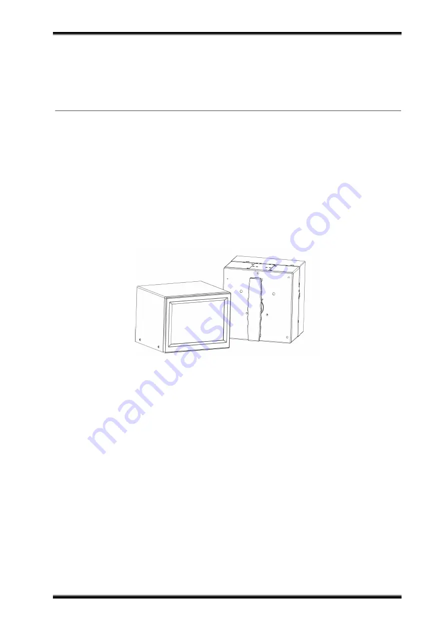
Page 8: ...2 0 9 1 2 Appearance and Components FC53 Li FC53 Lc FC53 Ri FC53 Rc consists of a printing device and a control device equipped with an operation interface control panel 1 Controller user interface 2...
Page 9: ...print head Ribbon cassette of printer body with ribbon supply shaft and old ribbon reel Controller device including main operation printed circuit board and user interface Connecting cable for print h...
Page 10: ...FC53 Rc Continuous Printer FC53 Lc FC53 Rc printer is specially designed for printing on a continuously moving substrate FC53 Lc FC53 Rc printer in this mode has a print area of 53 mm x 100 mm and a p...
Page 11: ...ser interface but device settings files can only be created by connecting to Format Designer These files can then be saved as setup files and attached to specific jobs Job FC53 Li FC53 Lc FC53 Ri FC53...
Page 12: ...m will be updated to print the new image 1 5 Retrieving and Downloading Jobs There are 3 methods to download job information Use the software Format Designer Use Format Designer for networking and a d...
Page 13: ...FC53 Li FC53 Lc FC53 Ri FC53 Rc User Manual Rev 2 0 14 2 In the Menu screen select File Management and then select Copy File...
Page 14: ...FC53 Li FC53 Lc FC53 Ri FC53 Rc User Manual Rev 2 0 15 3 Select Copy the file from USB drive...
Page 15: ...ly shaft slips Ribbon recycling shaft slips Incorrect print mode setting Ribbon detection check failed Ribbon motion detection damaged Magnetic destruction of the ribbon s moving axis Ribbon diameter...
Page 16: ...discharge life is at least 3 years Detector Ribbon tension detection thermal head position detection cover open detection TPH over temperature detection ribbon break detection Flexible Packaging Inspe...
Page 17: ...251 1252 1253 1254 1255 1257 UTF 8 UTF 16BE UTF 16LE DBCS 932 JIS 936 GBK 949 Koran 950 BIG5 1D Barcode Code 39 Code 93 EAN 8 13 add on 2 5 UPC A E add on 2 5 I 2 of 5 I 2 of 5 with carrier Kudbar cod...
Page 18: ...ware Interface Port Input Print Start and a configurable input Outputs fault warning and 2 configurable outputs Power Supply Internal switching power supply module I P AC90V 264V 47 63 Hz 150 VA Softw...
Page 19: ...C53 Rc user interface supports a variety of screen types The screen interface is generally divided into a central home screen and option buttons arranged vertically on both sides The rightmost column...
Page 20: ...iption Type of Screen Description Home screen Home screen where the user first started Menu screen To navigate between different menu options or screen types Diagnostic screen To display real time dyn...
Page 21: ...reen is the screen from which the user started to operate This screen can be the Ready screen or the Printing screen Various menus are accessible through the screens of both versions For example Ready...
Page 22: ...3 2 1 2 Menu Screen Navigate the menu by selecting the desired option button When you enter a menu the top item in the list is highlighted You can select the green back arrow at the bottom left of the...
Page 23: ...displayed is read only and cannot be changed This screen allows you to access the following information Input status current substrate speed Temperature print head temperature Ribbon Supply Ribbon Di...
Page 24: ...anual Rev 2 0 25 2 1 4 Fault and Warning Screen These screens inform you of current or potential problems A description of the problem appears on the screen When a fault occurs a warning message is di...
Page 25: ...26 3 Operation 3 1 Turn On the Printer 1 Press the power button on the back of the controller to turn on the controller After powering on the printer performs a self test 2 The controller home screen...
Page 26: ...FC53 Li FC53 Lc FC53 Ri FC53 Rc User Manual Rev 2 0 27 3 2 Stop the Printer Press the Pause key to stop the printer...
Page 27: ...FC53 Li FC53 Lc FC53 Ri FC53 Rc User Manual Rev 2 0 28 3 3 Print Adjustment Screen Select Print Adjustment on the main screen to adjust the print darkness and print position...
Page 28: ...FC53 Rc User Manual Rev 2 0 29 3 4 Remove the Ribbon Cassette 1 Rotate the locking lever on the cassette to the open position 2 Use the handle to remove the ribbon cassette 3 Remove the waste ribbon f...
Page 29: ...move Waste Ribbon from the Waste Take up Core 2 Push the tray back to its original position 3 Remove the waste ribbon by hand Note Do not use sharp objects such as screwdrivers to move the ribbon as t...
Page 30: ...core as indicated 3 Make sure the ribbon is free of any crease by rotating the waste take up reel by hand 4 Make sure that the ribbon is tracking parallel on the cassette rollers and is placed correct...
Page 31: ...d wind it around the waste ribbon reel 4 Turn the waste reel at least one revolution by hand to make the connection between the two ribbons as flat as possible Note If this step is not performed corre...
Page 32: ...to lock the device 4 When the ribbon cassette returns to its original position and the key switch is turned to READY I the FC53 Li FC53 Lc FC53 Ri FC53 Rc will automatically drive the print head to r...
Page 33: ...el The heat of the printing point will melt the ink and the pressure between the print head and the substrate will transfer the ink to the substrate FC53 Li FC53 Lc FC53 Ri FC53 Rc equipment uses the...
Page 34: ...the printer body and secured the ribbon supply shaft and the waste ribbon rewind shaft will be connected to the ribbon drive motor clutch The FC53 Li FC53 Ri intermittent printer uses a thermal print...
Page 35: ...3 Li FC53 Lc FC53 Ri FC53 Rc User Manual Rev 2 0 36 4 Printer Configuration 4 1 Access Menu Select Menu on the home screen The main menu screen is displayed The following options are accessible as nee...
Page 36: ...re Function Item Home screen Print Button Stop Button Fault Warning Menu Select Task Information Print Adjustment Clear Database Count Consumables Print Darkness Horizontal Offset Vertical Offset Vers...
Page 37: ...Statistics Ribbon Log Record Diagnosis Manual Control Input Status Temperature Ribbon Internal Ribbon Test Print Head Test Print Head Test Clear Print Database Copy the log to a USB drive Admin Mode...
Page 38: ...2 0 39 4 3 Setting Menu 1 Select Setting on the menu screen 2 Enter the device setting Note Most of the above settings should be configured immediately after installation Other settings such as print...
Page 39: ...speed minimum print speed mirror mode and ribbon saving mode Note 1 The maximum substrate speed is the upper limit of the substrate speed during printing It can be set to 100 200 300 400 500 600mm s 2...
Page 40: ...FC53 Li FC53 Lc FC53 Ri FC53 Rc User Manual Rev 2 0 41 3 Set the specified task date Home Click Enter Template Editor Click Properties Edit Time Selection Click Finish...
Page 41: ...al Defibrillation distance setting minimum 0 0 mm maximum 5 0 mm Package length 30 mm 1600 mm Fixed pitch distance setting minimum 30 mm maximum 1600 mm Missing print threshold setting minimum 0 maxim...
Page 42: ...e contrast TPH press down distance and TPH raised distance Note Print darkness setting minimum 80 maximum 125 Print darkness adjustment minimum 25 maximum 25 Contrast 4 60 99 Contrast 5 50 140 TPH pre...
Page 43: ...tion You can set horizontal offset maximum offset range minimum offset range and vertical offset Note Horizontal offset setting minimum 0 mm maximum 50 mm Maximum minimum offset range setting minimum...
Page 44: ...etection Yes No Insufficient ribbon threshold setting minimum 10 meters maximum 400 meters Insufficient ribbon operation Continue discard Log Record You can set log operations log overflow operations...
Page 45: ...on the menu screen to view various information about the status of the printer 4 4 1 Diagnosis Select Diagnosis to query the input status temperature ribbon and internal information Input status Displ...
Page 46: ...f the currently supplied ribbon and rewinding ribbon Internal Display the position of the tension controller the status of the ribbon cassette switch the number of connection errors between the contro...
Page 47: ...rol to query information about ribbon test and TPH test Ribbon Test You can choose to start or stop the ribbon feed The images selected for the print head test include ASCII code self test page slash...
Page 48: ...elect Service on the menu screen to set the upgrade from a USB flash drive Note After clicking to upgrade from a USB flash drive search for all the upgrade files in the upd file format on the USB flas...
Page 49: ...FC53 Li FC53 Lc FC53 Ri FC53 Rc User Manual Rev 2 0 50 4 6 Version Information Select Version on the menu screen to view the current hardware and software version...
Page 50: ...access the following options copy file delete file file statistics clear print database copy the log to the USB drive and pull error log Copy File You can copy files to the USB drive or copy files fr...
Page 51: ...FC53 Li FC53 Lc FC53 Ri FC53 Rc User Manual Rev 2 0 52 Delete File You can choose different types of files to delete Clear print database delete all files in the database...
Page 52: ...FC53 Li FC53 Lc FC53 Ri FC53 Rc User Manual Rev 2 0 53 File Statistics You can view the current total storage capacity and available storage capacity...
Page 53: ...nistrator Mode on the menu screen and enter the password the default password is 123456 to enter the administrator mode After entering the administrator mode according to user requirements click the o...
Page 54: ...g Only support continuous printers FC53 Lc FC53 Rc You can set the type direction resolution and diameter of the synchronizer Note Synchronizer type setting internal external single channel pulse exte...
Page 55: ...FC53 Ri FC53 Rc User Manual Rev 2 0 56 Ribbon Setting You can set the ribbon model ribbon width ribbon length and ribbon thickness System Clock Adjustment You can set the date and time of the device s...
Page 56: ...FC53 Li FC53 Lc FC53 Ri FC53 Rc User Manual Rev 2 0 57...
Page 57: ...53 Li FC53 Lc FC53 Ri FC53 Rc User Manual Rev 2 0 58 Restore Factory Setting Click Restore the factory setting a pop up dialog box Whether to clear the local cache is displayed Click to set successful...
Page 58: ...FC53 Rc User Manual Rev 2 0 59 IP Setting Click DHCP the system will automatically read the IP information if you click Static IP the user will set the IP address and other information according to t...
Page 59: ...C53 Li FC53 Lc FC53 Ri FC53 Rc User Manual Rev 2 0 60 Pamel Upgrade You can upgrade the pamel Extra Function You can perform the Import TPH_Extension function System Upgrade You can upgrade the system...
Page 60: ...FC53 Li FC53 Lc FC53 Ri FC53 Rc User Manual Rev 2 0 61 4 9 Select Task 1 Choose Select Task on the home screen 2 Select the file you want to print...
Page 61: ...FC53 Li FC53 Lc FC53 Ri FC53 Rc User Manual Rev 2 0 62 3 Select to set the file as the default job 4 10 Information 1 Choose Information on the home screen...
Page 62: ...i FC53 Rc User Manual Rev 2 0 63 2 Enter the Information screen to query the count material usage print history and task info Count You can view information such as normal print qty missing print qty...
Page 63: ...FC53 Rc User Manual Rev 2 0 64 Consumables consumption You can check the remaining ribbon the remaining printing the remaining time of the ribbon TPH print length and total print length Print history...
Page 64: ...FC53 Li FC53 Lc FC53 Ri FC53 Rc User Manual Rev 2 0 65 Task Info Query the editor version 4 11 Print Adjustment 1 Choose Print Adjustment on the home screen...
Page 65: ...er Manual Rev 2 0 66 2 Enter the Print Adjustment screen you can adjust the print darkness print position and package length Print Darkness You can set the print darkness and the selection range is 80...
Page 66: ...c FC53 Ri FC53 Rc User Manual Rev 2 0 67 Vertical Offset The vertical offset distance can be set and the selection range is 0 600mm continuous printerFC53 Lc FC53 Rc 0 750mm for intermittent printer F...
Page 67: ...FC53 Li FC53 Lc FC53 Ri FC53 Rc User Manual Rev 2 0 68 Horizontal Offset You can set the horizontal offset distance the selection range is 0 50mm Print Rotation 0 90 180 270 can be set...
Page 68: ...FC53 Li FC53 Lc FC53 Ri FC53 Rc User Manual Rev 2 0 69 Package Length The package length can be set and the selection range is 30 mm 1600 mm...
Page 69: ...rint head daily check Use isopropanol wipes to clean Check if the ribbon passes the ribbon cassette correctly Pull the ribbon through by hand visually check to see if the ribbon is wrinkling across th...
Page 70: ...its related components pulleys bearing retainers and shafts Check the air cylinder Make sure that the tension roller slide is free to move 5 2 3 Maintaining the Print Head Although specifically desig...
Page 71: ...setting that provides the required print quality 5 3 Cleaning the Print Head The print head should be cleaned regularly The frequency of cleaning depends on the use of the equipment the operating env...
Page 72: ...FC53 Li FC53 Lc FC53 Ri FC53 Rc User Manual Rev 2 0 73 5 4 Replace Print Head 5 4 1 Remove the Damaged Print Head 1 Remove the 3 6mm screw 2 Remove the two screws sized 3 6mm at the bottom...
Page 73: ...box power switch Precautions When installing D type connectors 4 5 and DC power connector 7 do not supply power to the device without ensuring that the connection is secure Interface Function and Sign...
Page 74: ...eserve 15 NC Reserve Start Print input port A Generate Start Print signal with PNP sensor Please connect as follows 1 Connect the detection signal line of the PNP sensor to pin 2 of DB15 Start printin...
Page 75: ...er air vent DB9 Port Signal Definition of Rotary Encoder Pin Signal definition Type 1 24V power POWER 2 GND 0V working ground of the system POWER 3 Encoder output signal A OUTPUT 4 Encoder output sign...
Page 76: ...aluminum alloy KE 941 black 2 Technical requirements 1 Need to be ground 2 End face is flat 3 Without beveling C0 2 deburring 4 The dimension with must be controlled 5 On axis hardness 47 50 6 Unmarke...