


Chapter 4 Electrical Installation
Shenzhen Hpmont Technology Co., Ltd.
-14-
HD3Z Series User Manual V1.2
4.4.1
Control Terminal
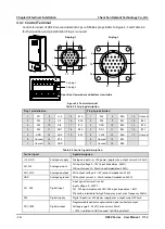
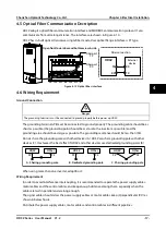
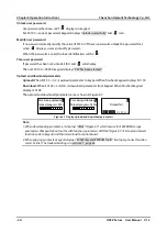
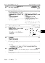
Control terminals of HD3Z are concluded into 3pcs of IP68 air plugs. Refer to Figure 4-3 and Table 4-4
for their position and pin definition. Plug 3 is unused.
Figure 4-3 Control terminal
Table 4-4 Air plug description
Plug 1 pin definition
Plug 2 pin definition
1
DI1
8
+10
15
R1A
1
DI5
8
R3A
15
Unused
2
DI2
9
AI1
16
R1B
2
DI6
9
R3C
16
R6C
3
DI3
10
AI2
17
R1C
3
GND
10
R4A
17
R7A
4
DI4
11
AO1
18
R2A
4
DO1
11
R4C
18
R7C
5
GND
12
AO2
19
R2C
5
CME
12
R5A
19
Unused
6
Unused
13
P24
6
Unused
13
R5C
7
Unused
14
GND
7
Unused
14
R6A
Table 4-5 Control signal description
Control signal
Signal description
+10, GND
Analogue supply
Analogue input use +10V power supply, max. output current is 100mA
AI1, AI2
Analogue input
AI1 input voltage 0 - 10V (input impedance: 32kΩ)
AI2 input current 0 - 20mA (input impedance: 500Ω)
AO1, AO2
Analogue output
AO1 output voltage: 0 - 10V (output impedance: 32kΩ)
AO2 output current: 0 - 20mA (output impedance: 500Ω)
GND
Analogue ground
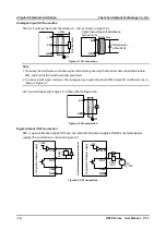
DI1 - DI6
Digital input
Input signal: low level is valid
Input voltage: 0 - 30VDC
DI1 - DI5 input impetance 4.7kΩ, DI6 input impedance 1.6kΩ
DI6 can be selectable for high-frequency input, max. frequency 50kHz
P24
Digital supply
Digital input use +24V power supply, max. output current 200mA
DO1, CME
Digital output
Programmable optical-couple isolation, open collector output
Voltage range: 0 - 30VDC, max. current 50mA
•
CME is isolated to GND, connect to GND by default
Air plug 1
1
21
24
4
5
9
10
16
15
20
1
3
4
7
8
12
13
16
17
19
Air plug 2
Air plug 1
Air plug 2
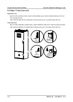
Open front lower door and bottom view inside